Introduction
This manual provides detailed instructions for the installation, operation, and maintenance of the QINIZX 5S-6S 5A Capacitor Active Equalizer Balancer. This device is designed to actively balance battery cells in LiFePO4 (LFP), Li-ion (NCM Ternary polymer lithium), and Lithium Titanate (LTO) battery packs, ensuring optimal performance and longevity.
Safety Information
WARNING: Improper installation or handling can lead to short circuits, damage to the board, or battery failure. Always exercise caution and follow instructions carefully.
- Ensure all battery connections are correct before connecting the balance cable to the board.
- Perform proper insulation for the bottom of the board and all battery string connection terminals to prevent short circuits.
- This product requires basic knowledge of electronics and hands-on skills for safe installation. If you are unsure, seek professional assistance.
- Do not short-circuit the mode selection (LTO/NCM/LFP) solder joints with the RUN solder joints, as this will damage the equalization board.
Product Overview
The QINIZX 5S-6S 5A Capacitor Active Equalizer Balancer utilizes a flying capacitor charge transfer mechanism to achieve active cell balancing. It is compatible with various lithium battery chemistries and features under-voltage sleep protection.
What's Included:
- 1x QINIZX Active Equalizer Balancer Board (PCBA)
- 1x Balance Cable (15.7 inches / 400mm length)
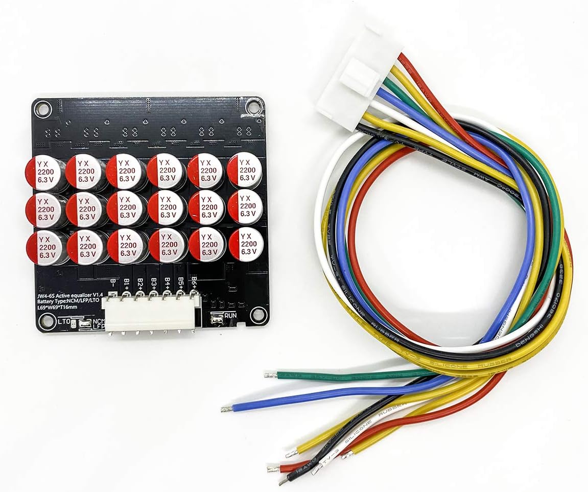
Image: The QINIZX 5S-6S Active Equalizer Balancer board shown with its included multi-colored balance cable. The board is black with several capacitors visible, and the cable has a white connector on one end and individual wires on the other.
Setup and Installation
1. Battery Type Selection
The balancer supports NCM (Li-ion), LFP (LiFePO4), and LTO (Lithium Titanate) battery types. The default setting is for NCM/LFP. If using LTO batteries, you must modify the solder joint on the board.
- For Li-ion (NCM) and LiFePO4 (LFP) Batteries: The board is configured by default. Ensure the "short connect" solder joint is in place for NCM/LFP.
- For LTO Batteries: Disconnect the default "short connect" solder joint for NCM/LFP and create a new "short connect" solder joint for LTO. Refer to the diagram below.

Image: Diagram illustrating the solder joint configurations for selecting battery types (Li-ion/LiFePO4 or LTO). It shows where to make or disconnect a short connection for each battery chemistry. A warning about not shorting mode selection with RUN solder joints is also present.
2. Wiring Connection
Connect the balance cable to your battery pack according to the cell count (4S, 5S, or 6S). The balancer is backward compatible; for example, if used for a 5S pack, the B6+ line will remain empty.
- Connect the B- wire to the negative terminal of the first cell (B1-).
- Connect B1+ to the positive terminal of the first cell (B1+).
- Continue connecting B2+, B3+, etc., to the positive terminals of subsequent cells.
- Ensure the last positive wire (e.g., B6+ for a 6S pack) is connected to the positive terminal of the last cell.

Image: Schematic diagrams showing the correct wiring connections for 4S, 5S, and 6S battery packs to the balance board. Each diagram illustrates the connection points for B-, B1+, B2+, B3+, B4+, B5+, and B6+.
Important: Double-check all connections for polarity and sequence before plugging the balance cable into the balancer board. Incorrect wiring can cause immediate damage.
3. External Switch (Optional)
The board has a "RUN" pad for an optional external switch to control the balancer's operation. By default, this pad is short-connected, allowing the balancer to work continuously. If you disconnect the default short and add an external switch, the balancer will only operate when the switch is closed.
- To enable manual control, disconnect the default short on the "RUN" pad.
- Connect an external switch to the "RUN" pads.
Caution: Do not short-circuit the mode selection (LTO/NCM/LFP) solder joints with the RUN solder joints. This will damage the equalization board.
Operating Instructions
Once correctly installed and connected, the balancer board will automatically begin its balancing operation. It uses a flying capacitor charge transfer method, where the entire battery pack participates in active equalization simultaneously.
- Balancing Current: The balance current ranges from 0-5.5A. A differential voltage of 0.1V typically results in a 1A equalizing current. The current increases with larger voltage differences between cells.
- Voltage Accuracy: The balance voltage accuracy is within 5mV.
- Quiescent Current: Approximately 7mA. For optimal performance, it is recommended for battery capacities between 30-200AH per balancer. Multiple equalizers can be connected in parallel for high-capacity batteries.
- LED Indicator: A single LED indicator will be continuously on during normal operation. If the LED is off, it indicates a problem or malfunction.
Under-Voltage Sleep Protection
The equalizer features under-voltage sleep protection. It monitors the voltage of the B1 battery cell. If the B1 voltage drops below a certain threshold, the equalizer will automatically enter a sleep state to prevent over-discharge of the battery.
- NCM/LFP Batteries: Sleep mode activates if B1 voltage is less than 2.7V.
- LTO Batteries: Sleep mode activates if B1 voltage is less than 1.8V.
- In sleep mode, the standby power consumption is less than 0.1mA.
Maintenance
The QINIZX Active Equalizer Balancer is designed for reliable operation with minimal maintenance. To ensure its longevity:
- Keep the board clean and free from dust and moisture.
- Regularly inspect all wiring connections for any signs of wear, corrosion, or loose contacts.
- Ensure adequate ventilation around the balancer, especially during operation, to prevent overheating.
Troubleshooting
- LED Indicator Off:
If the LED indicator is off during expected operation, it suggests a problem or malfunction. Check the following:
- Verify all balance cable connections are secure and correctly wired to the battery pack.
- Check if the battery pack voltage is above the under-voltage sleep protection threshold (NCM/LFP > 2.7V, LTO > 1.8V).
- If an external switch is used on the "RUN" pad, ensure it is in the "on" or closed position.
- Inspect the board for any visible damage or signs of short circuits.
- No Balancing Activity:
If the cells are not balancing as expected, ensure the battery type selection solder joint is correctly configured for your battery chemistry.
- Overheating:
While the board is designed for efficient operation, excessive heat can indicate an issue. Ensure proper ventilation and that the balancer is not overloaded beyond its recommended capacity (30-200AH per balancer).
Specifications
| Feature | Description |
|---|---|
| Working Voltage | 1.8V-4.5V |
| Compatible Battery Types | NCM Ternary polymer lithium (Li-ion), Lithium Iron Phosphate (LiFePO4), Lithium Titanate (LTO) |
| Balancing Principle | Flying capacitor transfer charge transporter (whole battery pack active equalization) |
| Balance Current | 0-5.5A (0.1V differential voltage = 1A current, proportional to voltage difference) |
| Balance Voltage Accuracy | Within 5mV |
| Quiescent Current | Approx. 7mA (for 5S-6S model) |
| Recommended Battery Capacity | 30-200AH per balancer |
| Under-Voltage Sleep Protection | NCM/LFP < 2.7V, LTO < 1.8V (B1 voltage detection) |
| Standby Power Consumption (Sleep Mode) | Less than 0.1mA |
| Board Dimensions (L x W x H) | 2.71 x 2.71 x 0.63 inches (69 x 69 x 16 mm) |
| Balance Cable Length | 15.7 inches (400 mm) |
| Working Temperature | -10°C to +60°C |
| External Power Supply Required | No (relies on internal energy transfer) |
| Model Number | JW-CAP-Balancer-6S |
| UPC/GTIN | 723258876158 |

Image: A table detailing the technical specifications of the active equalizer balancer, including available strings, battery types, voltage ranges, equalization accuracy, current, sleep protection, static current, product size, working temperature, and power supply requirements.
Cascade Mode (Advanced)
For battery packs with higher cell counts than a single balancer supports, multiple balancers can be connected in cascade mode. Theoretically, there is no limit to the number of balancers that can be cascaded.

Image: A schematic diagram illustrating how to connect multiple active equalizer balancers in cascade mode for higher cell count battery packs. It shows two balancer units, labeled NS and XS, connected in series to balance a larger battery string.
Warranty
This QINIZX product comes with a manufacturer warranty for 90 days from the date of purchase. Please retain your proof of purchase for warranty claims.
Support
For further assistance or technical inquiries, please refer to the seller's contact information on the platform where the product was purchased. Ensure you have your model number (JW-CAP-Balancer-6S) and purchase details ready.


