1. Introduction
The INGCO DM200 Digital Multimeter is a versatile and essential tool designed for measuring various electrical parameters. It provides accurate readings for voltage, current, and resistance, making it suitable for a wide range of electrical testing and troubleshooting tasks. This manual provides detailed instructions for the safe and effective use of your DM200 multimeter.
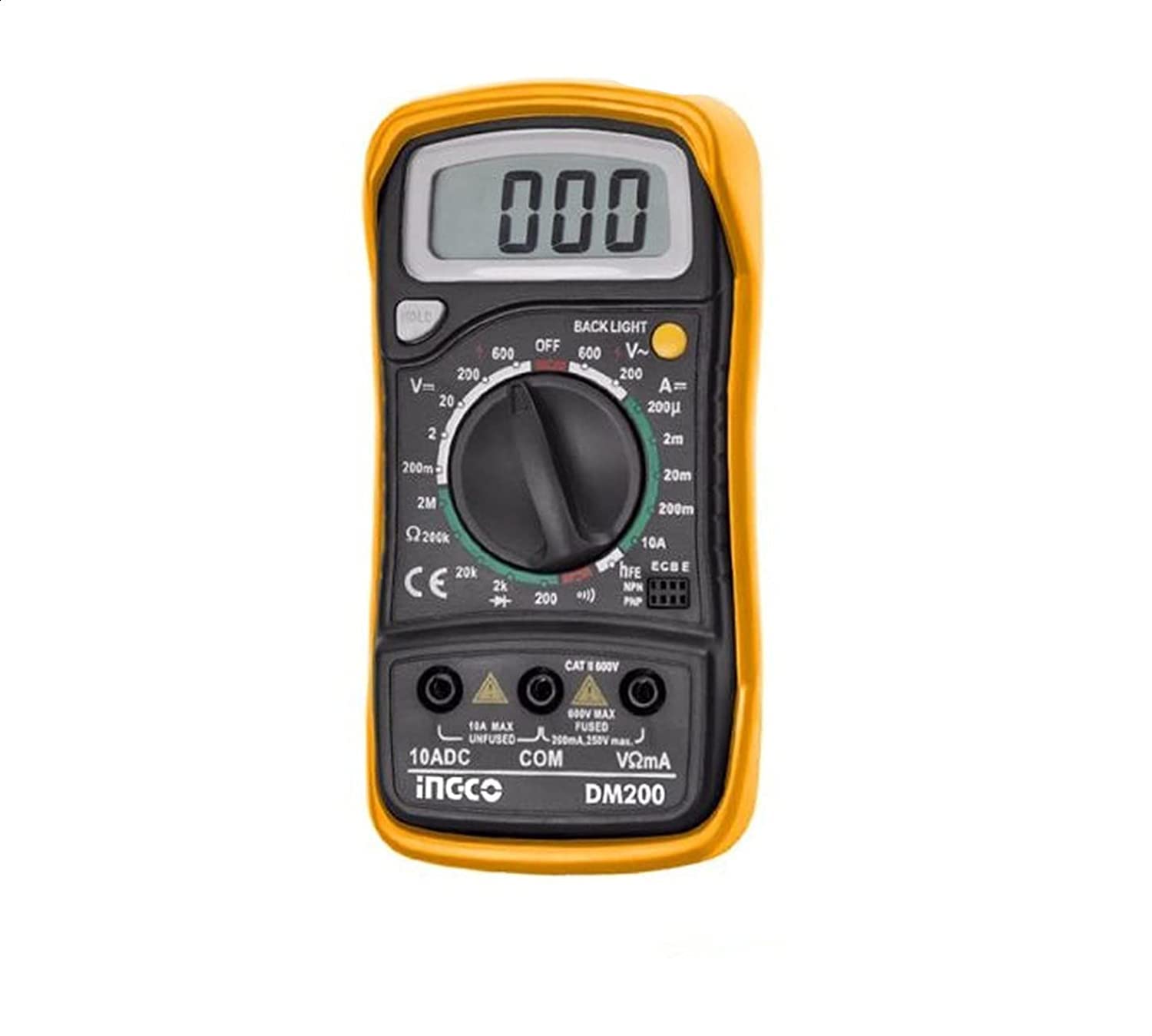
Figure 1: Front view of the INGCO DM200 Digital Multimeter. This image shows the device's display, rotary switch, and input jacks.
2. Safety Information
Always adhere to basic safety precautions when using electrical test equipment to reduce the risk of fire, electric shock, or personal injury. Read and understand all instructions before use.
- Do not exceed the maximum input limits for any measurement range. The DM200 is rated for a maximum voltage of 200V.
- Inspect test leads for damaged insulation or exposed metal before each use. Replace if damaged.
- Ensure the multimeter is set to the correct function and range before connecting to a circuit.
- Avoid contact with live circuits when connecting or disconnecting test leads.
- Use caution when working with voltages above 30V AC RMS, 42V peak, or 60V DC. These voltages pose a shock hazard.
- Do not operate the multimeter if it appears damaged or if it is not operating properly.
- Remove test leads from the circuit before changing functions or ranges.
3. Product Overview
The INGCO DM200 Digital Multimeter features a practical design for enhanced comfort and control. It includes a clear LCD display with backlight for easy reading of measurements, even in low-light conditions. The display shows up to 1999 counts.
Key Components:
- LCD Display: Shows measurement readings, units, and other indicators. Features a backlight.
- Rotary Switch: Used to select measurement functions (Voltage, Current, Resistance) and ranges.
- Input Jacks: Terminals for connecting test leads. Typically include COM (common), VΩmA, and 10A (for high current measurements).
- Test Leads: Red and black probes for connecting the multimeter to the circuit under test.
4. Setup
Before using your DM200 multimeter, follow these steps for initial setup:
- Battery Installation: The multimeter requires batteries for operation. Open the battery compartment on the back of the device (usually secured with screws) and insert the required batteries, observing correct polarity. Close the compartment securely.
- Connect Test Leads:
- Insert the black test lead into the COM (common) jack.
- For most measurements (voltage, resistance, low current), insert the red test lead into the VΩmA jack.
- For high current measurements (if applicable and within the device's capabilities), insert the red test lead into the dedicated 10A jack.
- Power On: Turn the rotary switch from the OFF position to the desired measurement function. The LCD display should illuminate.
5. Operating Instructions
The DM200 can measure voltage, current, and resistance. Always ensure the multimeter is set to the correct function and range before connecting to a circuit.
5.1. Measuring DC Voltage (VDC)
- Turn the rotary switch to the desired DC Voltage (VDC) range. Start with the highest range if the voltage is unknown, then decrease as needed for better resolution. The maximum measurable voltage is 200V.
- Connect the red test lead to the positive (+) side of the circuit and the black test lead to the negative (-) side.
- Read the voltage value on the LCD display.
5.2. Measuring AC Voltage (VAC)
- Turn the rotary switch to the desired AC Voltage (VAC) range. Start with the highest range if the voltage is unknown. The maximum measurable voltage is 200V.
- Connect the test leads across the component or circuit where you want to measure AC voltage. Polarity is not critical for AC measurements.
- Read the voltage value on the LCD display.
5.3. Measuring Resistance (Ω)
Warning: Ensure the circuit is completely de-energized before measuring resistance. Disconnect power and discharge any capacitors.
- Turn the rotary switch to the desired Resistance (Ω) range.
- Connect the test leads across the component whose resistance you want to measure.
- Read the resistance value on the LCD display.
5.4. Measuring DC Current (mA/A)
Warning: Current measurements require the multimeter to be connected in series with the circuit. Never connect the multimeter in parallel when measuring current, as this can damage the device and the circuit.
- Turn the rotary switch to the desired DC Current (mA or A) range.
- De-energize the circuit.
- Open the circuit at the point where you want to measure current.
- Connect the multimeter in series: the red test lead to the higher potential side of the break, and the black test lead to the lower potential side.
- Re-energize the circuit.
- Read the current value on the LCD display.
- De-energize the circuit again before disconnecting the multimeter and restoring the circuit.
6. Maintenance
Proper maintenance ensures the longevity and accuracy of your DM200 multimeter.
- Cleaning: Wipe the case with a damp cloth and mild detergent. Do not use abrasives or solvents.
- Battery Replacement: When the low battery indicator appears on the display, replace the batteries promptly to ensure accurate readings. Refer to the 'Setup' section for battery installation instructions.
- Fuse Replacement: If the current measurement function stops working, the fuse may be blown. Refer to the device's internal diagram (if available) or contact customer support for fuse specifications and replacement instructions. Always replace with a fuse of the same type and rating.
- Storage: If the multimeter will not be used for an extended period, remove the batteries to prevent leakage. Store in a cool, dry place.
7. Troubleshooting
If you encounter issues with your DM200 multimeter, refer to the following common problems and solutions:
| Problem | Possible Cause | Solution |
|---|---|---|
| No display or dim display | Dead or low batteries | Replace batteries. |
| Incorrect readings | Incorrect function/range selected; Damaged test leads; Poor contact; Blown fuse (for current) | Select correct function/range; Inspect/replace test leads; Ensure good contact; Check/replace fuse. |
| Current measurement not working | Blown fuse; Incorrect lead connection; Incorrect range | Check/replace fuse; Ensure red lead is in 10A jack for high current; Select appropriate current range. |
| "OL" (Overload) displayed | Measurement exceeds selected range; Open circuit (for resistance/continuity) | Select a higher range; Check for open circuit. |
If the problem persists after attempting these solutions, contact INGCO customer support for further assistance.
8. Specifications
The following specifications apply to the INGCO DM200 Digital Multimeter:
- Manufacturer: INGCO
- Model: DM200
- Display: 1999 Counts, LCD with Backlight
- Measurement Type: Multimeter (Voltage, Current, Resistance)
- Maximum Voltage Measurement: 200 Volt
- Resistance Measurement Range: Up to 200 Ohm (specific range may vary by model variant)
- Power Source: Corded Electric (This specification seems to be an error in the source data, as multimeters are typically battery-powered. Please refer to the product packaging for accurate power requirements.)
- Product Dimensions: 10 x 20 x 37 cm
- Item Weight: 209 grams
- Color: Multi
9. Warranty and Support
For warranty information and customer support, please refer to the documentation included with your product packaging or visit the official INGCO website. Keep your purchase receipt as proof of purchase for any warranty claims.
If you require technical assistance or have questions regarding the operation of your INGCO DM200 Digital Multimeter, please contact INGCO customer service.


