1. Introduction
This user manual provides essential information for the safe and efficient operation of the Qinlorgo A2-8075 Frequency Inverter. Please read this manual thoroughly before installation, operation, or maintenance to ensure proper usage and prevent damage or injury.
1.1 Safety Warnings
WARNING: High voltage inside.
- Do not connect AC power to output terminals (U, V, W).
- Discharging time is greater than 5 seconds.
- Do not inspect components unless the "CHARGE" lamp is turned OFF.
- Ensure proper grounding before connecting the device.
- Only qualified personnel should perform installation and maintenance.

Figure 1.1: Front view of the A2-8075 Frequency Inverter, highlighting the control panel and the high voltage warning label. The label explicitly states "CAUTION: High voltage inside" and lists critical safety precautions regarding power connection, discharge time, and inspection.
2. Product Overview
The Qinlorgo A2-8075 is a 3-phase frequency inverter designed for various industrial applications, including winding machines, mixers, extruders, conveyors, and splitters. It features a flame-retardant casing and a user-friendly control panel.
2.1 Components and Features
- Digital Display: Shows operational status and parameters.
- Control Buttons: RUN, STOP/RESET, SET, REV/FWD, JOG for easy operation.
- Cooling Vents: Located on the sides for heat dissipation.
- Input/Output Terminals: Clearly labeled for power and motor connections.
- Flame-retardant Casing: Enhances safety in industrial environments.
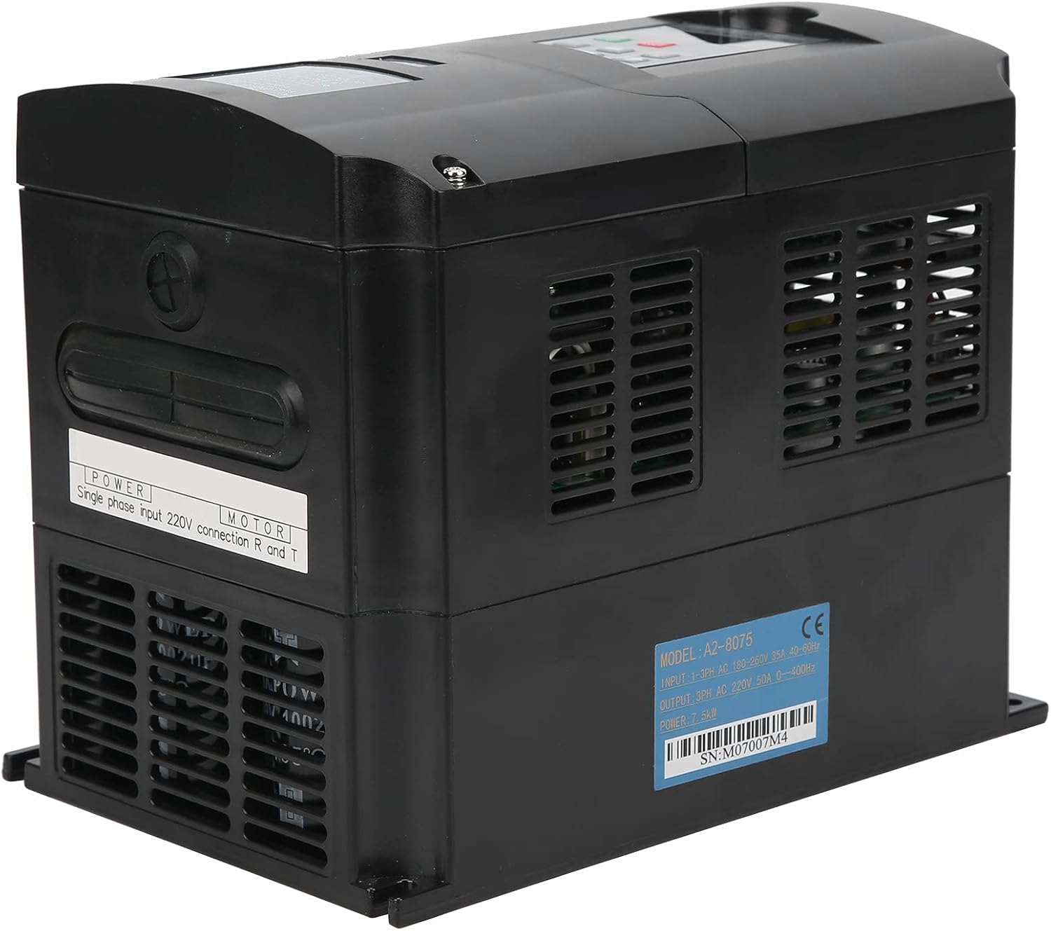
Figure 2.1: Side view of the A2-8075 Frequency Inverter. This image shows the cooling vents on the side and a label indicating "POWER Single phase input 220V connection R and T" for power input.

Figure 2.2: Angled view of the A2-8075 Frequency Inverter, providing a clearer look at the control panel and the extensive ventilation on the sides, crucial for heat management during operation.
3. Specifications
Technical specifications for the A2-8075 Frequency Inverter:
| Parameter | Value |
|---|---|
| Model | A2-8075 |
| Input Voltage | 250 Volts |
| Output Voltage | 220 Volts |
| Wattage | 7.5 KW |
| Power Source | Battery Powered (Note: Typically refers to the control circuit, main power is AC) |
| Item Weight | 6.51 pounds (approx. 2.95 kg) |
| Manufacturer | Qinlorgo |
| Serial Number (Example) | M07007M4 |

Figure 3.1: Rear view of the A2-8075 Frequency Inverter, displaying the product label with "MODEL: A2-8075" and an example serial number "SN: M07007M4". This label also details input/output specifications.

Figure 3.2: Dimensions of the A2-8075 Frequency Inverter. The image indicates a height of 220mm (8.7in), a depth of 180mm (7.1in), and a width of 150mm (5.9in), providing crucial information for installation planning.
4. Setup and Installation
Proper installation is crucial for the safe and reliable operation of the frequency inverter. Ensure all power is disconnected before beginning installation.
4.1 Mounting
- Choose a dry, well-ventilated area, free from direct sunlight, excessive dust, corrosive gases, and vibrations.
- Mount the inverter vertically on a stable surface, ensuring adequate clearance for cooling (refer to Figure 3.2 for dimensions).
- Ensure the ambient temperature is within the operating range specified in the full technical datasheet (not provided here).
4.2 Wiring
All wiring must comply with local electrical codes and regulations. Use appropriate wire gauges for the power and motor connections.
- Power Input: Connect the 3-phase AC power supply to the designated input terminals (R, S, T). Ensure the input voltage matches the inverter's specifications (250V).
- Motor Output: Connect the motor to the output terminals (U, V, W). Do not connect AC power to these terminals.
- Grounding: Connect the inverter to a reliable earth ground using the designated ground terminal. This is critical for safety.
- Control Wiring: Refer to the full wiring diagram (not provided in this manual) for connecting external control signals, such as start/stop, speed reference, and fault indicators.
5. Operating Instructions
This section outlines the basic operation of the A2-8075 Frequency Inverter using its control panel.
5.1 Control Panel Overview
Figure 5.1: Detailed view of the A2-8075 control panel. It features a 4-digit 7-segment display and buttons for RUN, STOP/RESET, SET, REV/FWD, and JOG, along with indicators for ERROR, FWD, REV, ANA, SEG, LOG, and MENT/PANEL.
- Digital Display: Shows frequency, current, voltage, and error codes.
- RUN Button (Green): Initiates motor operation.
- STOP/RESET Button (Red): Stops motor operation and resets fault conditions.
- SET Button: Enters parameter setting mode and confirms selections.
- REV/FWD Buttons (Up/Down Arrows): Adjusts frequency or navigates parameters.
- JOG Buttons (Left/Right Arrows): Used for momentary operation or specific parameter adjustments.
5.2 Basic Operation Sequence
- Power On: Ensure all connections are secure and apply power to the inverter. The digital display should light up.
- Parameter Setting (if necessary): Use the SET button to enter parameter mode. Navigate with REV/FWD and JOG buttons to set desired frequency, acceleration/deceleration times, and other motor parameters. Refer to the comprehensive programming manual for detailed parameter descriptions.
- Start Motor: Press the RUN button. The motor should begin to accelerate to the set frequency.
- Adjust Frequency: While running, use the REV/FWD buttons to adjust the output frequency and thus the motor speed.
- Stop Motor: Press the STOP/RESET button. The motor will decelerate and stop.
- Reset Fault: If an error occurs, the display will show an error code. Address the cause of the error, then press the STOP/RESET button to clear the fault.
6. Maintenance
Regular maintenance ensures the longevity and optimal performance of your A2-8075 Frequency Inverter. Always disconnect power before performing any maintenance.
- Cleaning: Periodically clean the exterior of the inverter with a soft, dry cloth. Do not use liquid cleaners or solvents.
- Ventilation: Ensure cooling vents (see Figure 2.1 and Figure 2.2) are free from dust and obstructions. Use compressed air to gently clear any accumulated dust from the heatsink fins.
- Connections: Regularly check all electrical connections for tightness. Loose connections can cause overheating and malfunction.
- Environmental Check: Monitor the operating environment to ensure it remains within specified conditions (temperature, humidity, dust levels).
- Capacitor Life: Electrolytic capacitors have a finite lifespan. While not user-serviceable, be aware that performance may degrade over many years of continuous operation.

Figure 6.1: Close-up view of the cooling fan located on the side of the A2-8075 Frequency Inverter. Regular inspection and cleaning of this fan are essential for maintaining proper airflow and preventing overheating.
7. Troubleshooting
This section provides solutions to common issues you might encounter with the A2-8075 Frequency Inverter. For complex problems, contact qualified service personnel.
| Problem | Possible Cause | Solution |
|---|---|---|
| Inverter does not power on. | No input power; loose connections; internal fuse blown. | Check power supply; verify all connections; consult service manual for fuse replacement (qualified personnel only). |
| Motor does not run. | Inverter in STOP mode; incorrect wiring; fault condition; motor issue. | Press RUN button; check motor and output wiring (U, V, W); check display for error codes and reset; test motor separately. |
| Overcurrent fault. | Motor overload; short circuit in motor or wiring; rapid acceleration. | Reduce motor load; check motor and wiring for shorts; increase acceleration time parameter; press STOP/RESET. |
| Overvoltage fault. | High input voltage; rapid deceleration; regenerative load. | Check input voltage; increase deceleration time parameter; consider adding a braking resistor if applicable. |
| Overheat fault. | Insufficient ventilation; high ambient temperature; blocked cooling fan. | Ensure proper airflow; clean cooling vents and fan; reduce ambient temperature; press STOP/RESET. |
8. Warranty and Support
The Qinlorgo A2-8075 Frequency Inverter is typically covered by a manufacturer's limited warranty against defects in materials and workmanship. The specific terms and duration of the warranty may vary based on your region and point of purchase.
- Warranty Claims: For warranty service, please retain your proof of purchase and contact the retailer or authorized distributor from whom you purchased the product.
- Technical Support: For technical assistance, troubleshooting beyond this manual, or inquiries about spare parts, please contact Qinlorgo customer support or visit their official website.
- Online Resources: Additional resources, including detailed wiring diagrams, programming guides, and firmware updates, may be available on the manufacturer's website.


