Yunir AT1-2200X
AT1-2200X Variable Frequency Drive Converter User Manual
Model: AT1-2200X | Brand: Yunir
1. Introduction
This manual provides detailed instructions for the installation, operation, and maintenance of the Yunir AT1-2200X Variable Frequency Drive (VFD) Converter. The AT1-2200X is designed to control the speed of 3-phase 2.2 kW AC motors, offering precise control and stable performance for various industrial and home applications. Please read this manual thoroughly before using the device to ensure safe and efficient operation.
2. Safety Precautions
Adhering to safety guidelines is crucial for preventing injury and damage to the equipment. Always observe the following precautions:
- Do not operate the VFD if it appears damaged or if any request may cause death, severe injury, or serious property loss.
- Before wiring, always ensure the power supply is cut off.
- It is forbidden to connect U, V, W output terminals directly to an AC power supply; doing so will cause damage to the inverter.
- The inverter must not be installed in flammable or explosive environments.
- The ground terminal of the inverter must be properly grounded.
- Only qualified personnel should perform wiring and internal maintenance of the converter. Opening the shell under high pressure is strictly prohibited.
- When setting parameters, ensure the VFD is not actively working, as parameter changes may not be saved otherwise.

Figure 2.1: Front panel of the AT1-2200X VFD, highlighting the safety precautions label.
3. Product Overview
The AT1-2200X VFD is a robust and reliable motor speed controller. It features a large heat sink for efficient cooling and a user-friendly interface for easy operation.

Figure 3.1: Main product view of the AT1-2200X VFD.
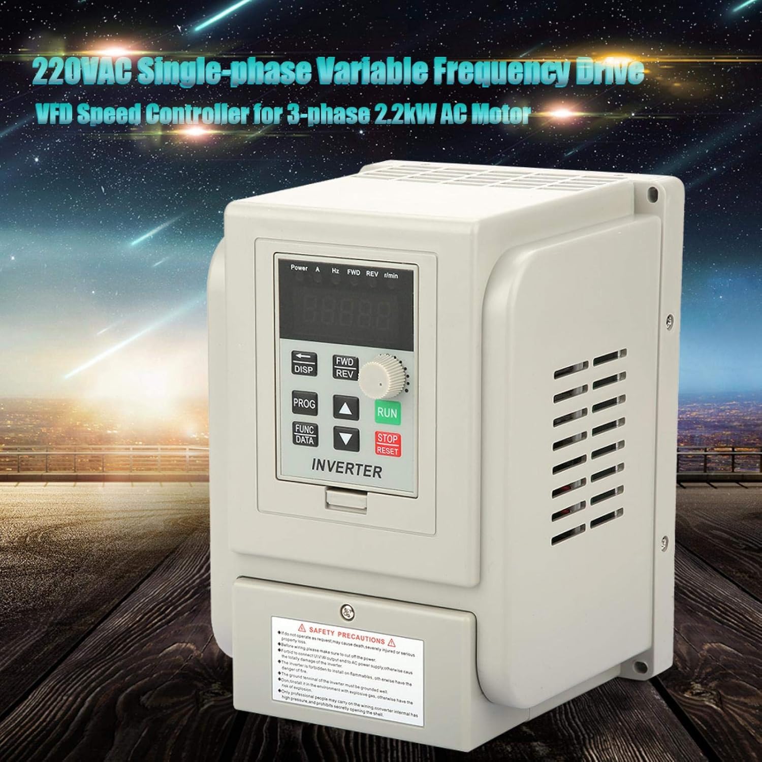
Figure 3.2: The AT1-2200X VFD in a typical operational environment.

Figure 3.3: Frontal view of the VFD, highlighting the control interface.

Figure 3.4: Side view of the VFD, illustrating its compact design.
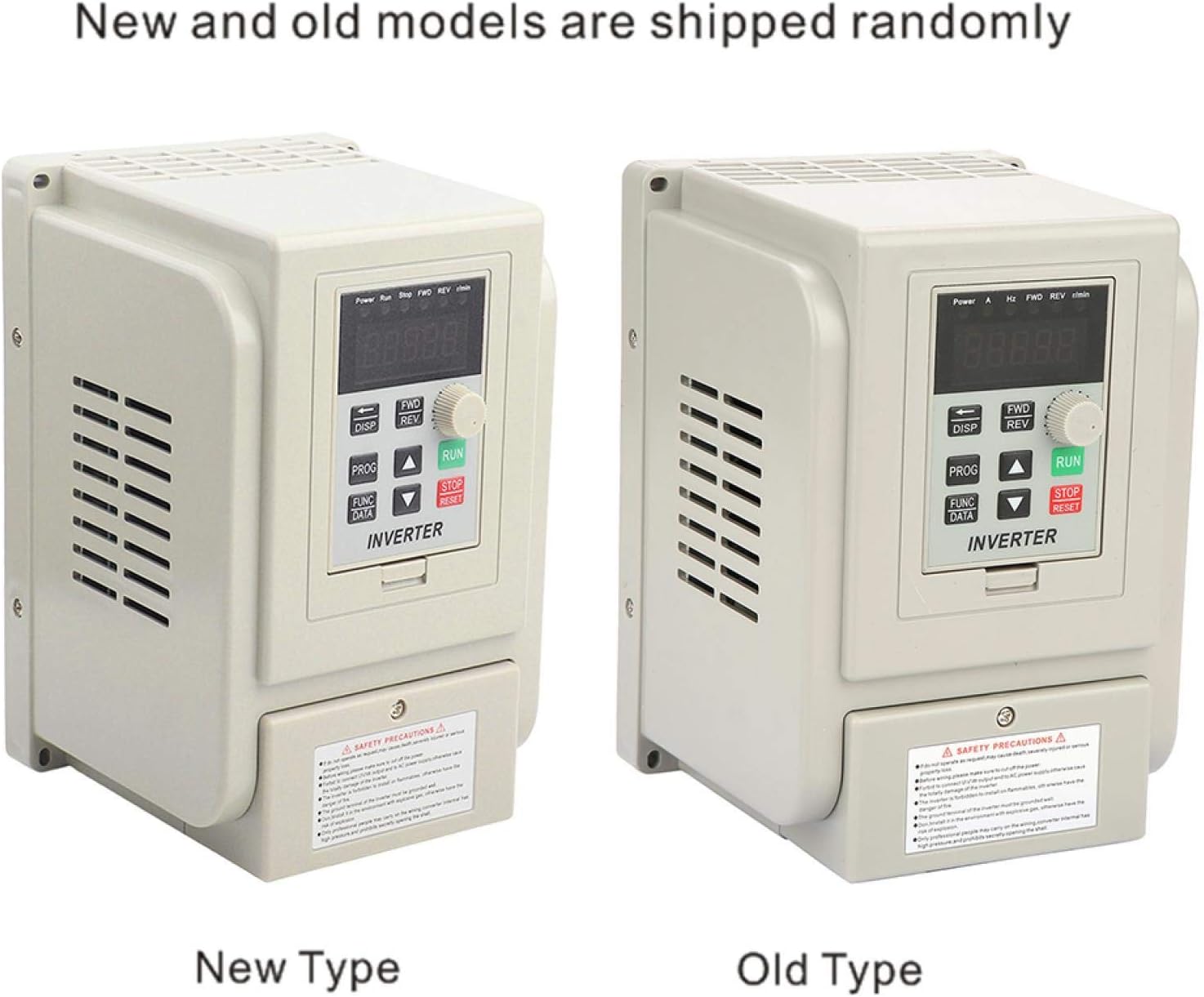
Figure 3.5: Comparison of new and old model types, shipped randomly.
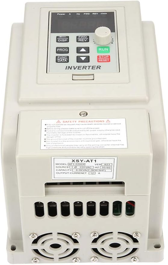
Figure 3.6: Bottom view with cooling fans and product information label.

Figure 3.7: Angled top-down view of the VFD.
4. Specifications
The following table details the technical specifications of the AT1-2200X VFD Converter:
| Parameter | Value |
|---|---|
| Model | AT1-2200X |
| Power Source Phase | Single-phase |
| Nominal Voltage | AC220V (Single-phase/Three-phase) |
| Supply Voltage Type | Low voltage |
| Suitable Motor Power | 2.2 kW |
| Filter | Built-in filter |
| DC Power Supply Type | Voltage type |
| Control Method | V/F control circuit |
| Output Voltage Setting Method | PWM control |
| Rated Current | 12A |
| Output Frequency | 400Hz |
| Dimensions (L x W x H) | 18 x 12.5 x 12.5 cm (7.1 x 4.9 x 4.9 inches) |
| Item Weight | Approx. 1.3 kg (2.99 pounds) |
| Color | Beige |
| Manufacturer | Yunir |
| Country of Origin | China |

Figure 4.1: Physical dimensions of the AT1-2200X VFD.
5. Setup and Installation
Proper wiring is essential for the safe and correct operation of the VFD. All connections should be made with the power supply disconnected.
5.1 Terminal Instructions
The VFD features various terminals for input, output, and control signals. Refer to the table below for terminal functions:
| Terminal | Description |
|---|---|
| COM | Common terminal |
| VI1 | External analog voltage input (0-5V/10V) |
| CI | External current input (4-20mA) |
| SP1 | Open collector output 1 |
| SP2 | Open collector output 2 |
| 5V/10V | 5V/10V power supply output |
| 20mA | 20mA power supply output |
| TC | Relay output (250 VAC 5A / 30 VDC 3A) - TA TC are Normally Open (NO) |
| TA | Relay output - TA TB are Normally Closed (NC) |
| TB | Relay output |
Wires can be connected using the screw terminals provided. Ensure all connections are secure and correctly aligned with the terminal functions.
6. Operating Instructions
The AT1-2200X VFD utilizes V/F control and PWM control for precise motor speed regulation. The front panel provides an intuitive interface for operation.
6.1 Control Panel Overview
Figure 6.1: Detailed view of the VFD control panel.
- Display: Shows current operating parameters such as power, current (A), frequency (Hz), forward/reverse status (FWD/REV), and revolutions per minute (r/min).
- DISP Button: Used to cycle through different display parameters.
- PROG/FUNC/DATA Buttons: Used for entering programming mode, selecting functions, and confirming data entries.
- Arrow Buttons (Up/Down/Left/Right): Used for navigating menus and adjusting parameter values.
- FWD/REV Buttons: Control the forward and reverse rotation of the motor.
- RUN Button: Initiates motor operation.
- STOP/RESET Button: Stops motor operation and resets alarms.
- Rotary Knob: Used for fine-tuning frequency or other adjustable parameters.
6.2 Basic Operation
- Power On: Connect the VFD to the appropriate single-phase 220V AC power supply. Ensure all wiring is correct and secure before powering on.
- Parameter Setting: If necessary, adjust operating parameters such as maximum frequency, acceleration/deceleration times, and motor parameters. Refer to the programming guide (not included in this manual, typically found in a separate detailed technical manual) for specific parameter codes and settings. Remember: Parameters cannot be saved if the VFD is actively running.
- Start Motor: Press the RUN button to start the motor. The display will show the current operating frequency and other relevant data.
- Adjust Speed: Use the rotary knob or arrow buttons to adjust the output frequency, thereby controlling the motor speed.
- Change Direction: Use the FWD or REV buttons to change the motor's rotation direction.
- Stop Motor: Press the STOP/RESET button to stop the motor.
7. Maintenance
Regular maintenance ensures the longevity and optimal performance of your AT1-2200X VFD.
- Cleaning: Keep the VFD clean and free from dust and debris. Use a soft, dry cloth for cleaning. Do not use liquid cleaners.
- Ventilation: Ensure that the ventilation openings and cooling fans are not obstructed. The VFD is designed with a large heat sink for effective cooling, which is vital for stability.
- Connections: Periodically check all wiring connections to ensure they are tight and secure. Loose connections can lead to poor performance or damage.
- Environment: Operate the VFD within its specified environmental conditions (temperature, humidity) to prevent premature wear.
8. Troubleshooting
The AT1-2200X VFD is equipped with various protection mechanisms. If an issue occurs, the VFD may display an error code or stop operation. Common protections include:
- Overcurrent Protection: Activates if the output current exceeds the rated limit. Check for motor overload or short circuits in the motor wiring.
- Overvoltage Protection: Triggers if the DC bus voltage exceeds a safe level, often due to regenerative braking or unstable input voltage.
- Overheating Protection: Engages if the internal temperature of the VFD becomes too high. Ensure proper ventilation and ambient temperature.
- Undervoltage Protection: Occurs if the input voltage drops below the minimum operating threshold. Verify the stability of the power supply.
- Short-circuit Protection: Detects short circuits in the output wiring to the motor. Inspect motor windings and cables.
In case of a fault, the VFD will typically stop and display an error. Consult a more detailed technical manual for specific error codes and advanced troubleshooting steps. Always disconnect power before inspecting or attempting repairs.
9. What's in the Box
Upon opening the package, you should find the following item:
- 1 x AT1-2200X Variable Frequency Drive Converter
10. Warranty and Support
For warranty information, technical support, or service inquiries regarding your Yunir AT1-2200X VFD Converter, please refer to the documentation provided with your purchase or contact Yunir customer service directly. Keep your purchase receipt as proof of purchase for any warranty claims.
Ask a question about this manual
Ask about setup, troubleshooting, compatibility, parts, safety, or missing instructions. Manuals+ will review the question and use this page’s manual context to help answer it.