1. Product Overview
The TP-Link TL-SL1311MP is an unmanaged 8-Port 10/100Mbps PoE+ Switch designed for reliable and flexible network expansion. It features 8 PoE+ ports, 2 Gigabit RJ45 uplink ports, and 1 Gigabit SFP slot, providing a total PoE budget of 124W. This switch is ideal for powering devices such as IP cameras, IP phones, and wireless access points.
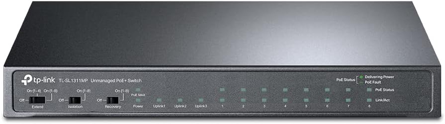
Figure 1: Front view of the TL-SL1311MP PoE+ Switch, showing LED indicators and mode switches.
1.1 Package Contents
- TL-SL1311MP Switch
- Power Adapter
- Installation Guide
2. Setup
The TL-SL1311MP switch is designed for plug-and-play operation, requiring no software installation or complex configuration. Simply connect your devices to the appropriate ports.
2.1 Connecting the Switch
- Connect the power adapter to the switch's power input and plug it into a power outlet.
- Connect your network router or main network device to one of the Gigabit RJ45 Uplink ports (Uplink1, Uplink2) or the Gigabit SFP slot using an Ethernet cable or SFP module.
- Connect your PoE-powered devices (e.g., IP cameras, IP phones, wireless access points) to the 8 PoE+ RJ45 ports (1-8).
- Connect non-PoE devices (e.g., computers, printers) to any of the available RJ45 ports.

Figure 2: Rear view illustrating the various port types on the TL-SL1311MP.

Figure 3: Example of a network setup utilizing the TL-SL1311MP for various devices.
3. Operating Modes
The TL-SL1311MP switch offers specialized operating modes to enhance network performance and security for specific applications.
3.1 Extend Mode
Extend Mode allows for extended PoE transmission distances up to 250 meters (820 feet) for data and power. This is particularly useful for surveillance systems where cameras may be located far from the switch. When Extend Mode is enabled, the speed for the affected ports will be downgraded to 10 Mbps.
To enable Extend Mode, use the 'Extend' switch on the front panel. You can choose to extend ports 1-4 or ports 1-8.

Figure 4: Extend Mode operation, enabling longer cable runs for PoE devices.
3.2 Isolation Mode
Isolation Mode enhances LAN security by isolating data traffic between specific PoE ports. This prevents broadcast storms and improves overall network security and data transmission efficiency, especially in scenarios where connected devices should not communicate directly with each other.
To enable Isolation Mode, use the 'Isolation' switch on the front panel. This typically isolates ports 1-8 from each other, allowing them to communicate only with the uplink ports.

Figure 5: Isolation Mode, enhancing security by segmenting traffic between ports.
3.3 PoE Auto Recovery
The PoE Auto Recovery feature automatically detects and reboots unresponsive PoE-powered devices. If a PoE device stops responding, the switch will automatically cut and restore power to that port, effectively restarting the device without manual intervention. This ensures continuous operation of critical devices like IP cameras.
To enable PoE Auto Recovery, use the 'Recovery' switch on the front panel.

Figure 6: PoE Auto Recovery in action, ensuring device uptime.
3.4 Intelligent Power Management
The switch features intelligent power management to prevent power overload. If the total power consumption of connected PoE devices exceeds the 124W budget, the switch will intelligently cut power to lower-priority ports to ensure that higher-priority devices remain powered and operational.

Figure 7: Intelligent Power Management, optimizing power distribution.
4. Maintenance
To ensure optimal performance and longevity of your TL-SL1311MP switch, consider the following maintenance guidelines:
- Placement: Place the switch in a cool, dry, and well-ventilated area away from direct sunlight, heat sources, and excessive dust.
- Cleaning: Regularly clean the exterior of the switch with a soft, dry cloth. Do not use liquid or aerosol cleaners.
- Ventilation: Ensure that the ventilation openings are not blocked to allow for proper airflow and heat dissipation.
- Cable Management: Organize network cables to prevent tangles and ensure proper airflow around the device.
5. Troubleshooting
If you encounter issues with your TL-SL1311MP switch, refer to the following common troubleshooting tips:
5.1 No Power
- Ensure the power adapter is securely connected to the switch and a working power outlet.
- Verify that the power outlet is functional by plugging in another device.
5.2 No Link/Activity on a Port
- Check the Ethernet cable connections at both ends. Try a different cable if necessary.
- Ensure the connected device is powered on and functioning correctly.
- Verify that the correct port is being used (e.g., PoE port for PoE devices).
- If using Extend Mode, ensure the connected device supports 10 Mbps speed.
5.3 PoE Device Not Receiving Power
- Confirm the device is PoE compatible (802.3at/af standard).
- Check the PoE+ port LED indicators on the switch.
- Ensure the total power consumption of all connected PoE devices does not exceed the 124W budget.
- Try connecting the device to a different PoE port.
- If PoE Auto Recovery is enabled, wait a moment to see if the device reboots automatically.
6. Specifications
| Feature | Description |
|---|---|
| Model Number | TL-SL1311MP |
| Ports | 8 × 10/100 Mbps PoE+ RJ45 Ports, 2 × Gigabit RJ45 Uplink Ports, 1 × Gigabit SFP Slot |
| PoE Standard | 802.3at/af compliant |
| PoE Power Budget | 124 W |
| Max Power Per Port | 30 W |
| Data Transfer Rate | 100 Megabits Per Second (Fast Ethernet), 1000 Megabits Per Second (Gigabit) |
| Extend Mode | Up to 250m PoE transmission (10 Mbps) |
| Isolation Mode | Supported |
| PoE Auto Recovery | Supported |
| Dimensions (L×W×H) | 8.2" x 4.9" x 1" (208.3mm x 124.5mm x 25.4mm) |
| Item Weight | 1.32 pounds (0.6 Kilograms) |
| Operating System Compatibility | Linux, Mac OS X, Windows |
7. Warranty and Support
7.1 Warranty Information
The TP-Link TL-SL1311MP switch is backed by an industry-leading 3-year warranty, ensuring peace of mind and product reliability.
7.2 Technical Support
Free technical support is available from 6 AM to 6 PM PST, Monday to Friday. For further assistance or detailed inquiries, please refer to the official TP-Link support channels or the comprehensive user manual PDF.
You can access the official User Manual (PDF) here.