1. Introduction
This manual provides detailed instructions for the Usmile Matek Micro BEC 6-60V Adjustable Step-Down Voltage Regulator (model mBEC12S). This compact module is designed to efficiently convert a wide input voltage range (6V to 60V) into a stable, selectable output of 5V, 9V, or 12V, making it ideal for powering various components in FPV racing quadcopters and similar electronic projects.

Figure 1: Usmile Matek Micro BEC 6-60V Voltage Regulator (mBEC12S)
2. Features
- Wide Input Voltage Range: Operates from 6V to 60V DC, compatible with 2S to 12S LiPo batteries.
- Adjustable Output Voltage: User-selectable output of 5V, 9V, or 12V. Default output is 5V.
- High Efficiency: Maximum Duty Cycle of 100%, meaning if the input voltage drops below the set output voltage, the regulator will pass through the input voltage directly.
- Low Standby Current: Consumes less than 5mA in standby mode.
- Protection Features: Includes Over Current Protection (OCP) with Hiccup mode and Thermal Shutdown.
- Short-Circuit Tolerant: Output is tolerant to short circuits for 3 seconds per minute.
- Compact Design: Small size (18x15x4.5mm) and lightweight (2g) for easy integration.
- Standard Pin Spacing: 2.54mm pin distance for convenient soldering.
3. Specifications
| Parameter | Value |
|---|---|
| Input Voltage | 6V - 60V DC (2S-12S LiPo) |
| Start-up Voltage | ≥ 6.7V |
| Output Voltage | 5V, 9V, or 12V (Adjustable, Default 5V) |
| Standby Current | < 5mA |
| Dimensions | 18mm x 15mm x 4.5mm |
| Weight | 2g |
| Pins Distance | 2.54mm |
| Protection | OCP, Thermal Shutdown, Output Short-circuit tolerant (3s/min) |
| Reverse Polarity Protection | None for input |

Figure 2: Dimension comparison of mBEC12S with a Micro SD card.
4. Setup and Wiring
Careful wiring is essential for proper function and to prevent damage. Refer to the diagram below for pin identification and connection points.
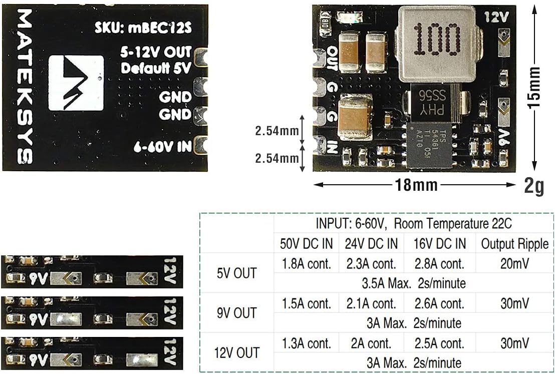
Figure 3: Wiring diagram, pinout, and output current table for mBEC12S.
4.1 Pinout
- IN: Positive input voltage (6V-60V).
- GND (Input): Ground connection for input power.
- OUT: Positive output voltage (5V, 9V, or 12V).
- GND (Output): Ground connection for output power.
4.2 Output Voltage Selection
The output voltage can be adjusted by bridging specific solder pads on the module. The default output is 5V when no pads are bridged.
- 5V Output: Leave all voltage selection pads unbridged.
- 9V Output: Bridge the middle solder pad.
- 12V Output: Bridge the rightmost solder pad.
Caution: Ensure only one voltage selection pad is bridged at a time. Bridging multiple pads or incorrect pads may damage the module or connected devices.
4.3 Connection Steps
- Prepare Wires: Solder appropriate gauge wires to the IN, GND (input), OUT, and GND (output) pads.
- Select Output Voltage: Bridge the desired solder pad for 5V, 9V, or 12V output.
- Connect Input Power: Connect the positive lead of your power source (e.g., LiPo battery) to the IN pad and the negative lead to the GND (Input) pad. Ensure correct polarity as there is no reverse polarity protection.
- Connect Output Device: Connect the positive power input of your device (e.g., flight controller, video transmitter) to the OUT pad and its ground to the GND (Output) pad.
- Verify Connections: Double-check all solder joints and wire connections for proper polarity and secure attachment before applying power.
5. Operating Instructions
Once correctly wired and the desired output voltage is selected, the Usmile Matek Micro BEC operates automatically upon receiving input power.
- Apply input voltage within the 6V to 60V range to the IN and input GND pads.
- The module will step down the voltage to the pre-selected 5V, 9V, or 12V output.
- Verify the output voltage with a multimeter before connecting sensitive components to ensure the correct voltage is being supplied.
Important: The continuous load current depends on the input voltage and heat dissipation. Ensure adequate airflow if operating at higher loads or input voltages to prevent thermal shutdown.
6. Maintenance
The Usmile Matek Micro BEC is a low-maintenance device. Follow these guidelines to ensure longevity:
- Keep the module clean and free from dust, dirt, and moisture.
- Regularly inspect solder joints and wire connections for any signs of wear, corrosion, or damage.
- Avoid exposing the module to extreme temperatures or direct sunlight for prolonged periods.
- Ensure proper ventilation, especially when operating under heavy loads, to prevent overheating.
7. Troubleshooting
If you encounter issues with your Micro BEC, consider the following troubleshooting steps:
- No Output Voltage:
- Check if the input voltage is within the specified range (6V-60V) and above the start-up voltage (≥6.7V).
- Verify input power connections for correct polarity and secure contact.
- Inspect for any short circuits on the output side. The module has short-circuit protection but prolonged shorts can cause issues.
- Ensure the module is not in thermal shutdown due to overheating. Allow it to cool down.
- Incorrect Output Voltage:
- Confirm that the correct solder pad for your desired output voltage (5V, 9V, or 12V) is properly bridged, and no other pads are bridged.
- Measure the input voltage. If the input voltage is below the selected output voltage, the output will match the input (due to 100% duty cycle).
- Module Overheating:
- Reduce the load on the output.
- Improve ventilation around the module.
- Ensure the input voltage is not excessively high for the current draw, which can increase heat generation.
8. Warranty and Support
For warranty information and technical support, please refer to the retailer where the product was purchased or contact the manufacturer directly. Keep your proof of purchase for any warranty claims.