1. Introduction
This manual provides essential information for the safe and efficient operation of your POWLAND 5000W Solar Inverter Charger. This device is an all-in-one unit combining a 5000W pure sine wave inverter, an 80A MPPT solar charge controller, and a battery charger. It is designed to provide uninterrupted power to various loads, supporting 48V lead-acid or lithium battery systems.
Please read this manual thoroughly before installation and use. Keep it for future reference.

Figure 1: Front view of the POWLAND 5000W Solar Inverter Charger.
2. Safety Information
Important Safety Instructions:
- Read all instructions and cautionary markings on the unit and in this manual before operating.
- This unit is designed for indoor use only. Do not expose it to rain, snow, or any type of liquid.
- Do not disassemble the unit. Refer servicing to qualified personnel. Incorrect reassembly may result in a risk of electric shock or fire.
- To reduce the risk of electric shock, disconnect all wiring before attempting any maintenance or cleaning.
- Ensure proper grounding. All wiring must comply with local and national electrical codes.
- Use only recommended accessories. Use of non-recommended attachments may result in a risk of fire, electric shock, or injury to persons.
- Keep children away from the unit.
- Do not operate the unit if it has received a sharp blow, been dropped, or otherwise damaged.
3. Product Overview
The POWLAND 5000W Solar Inverter Charger is a versatile power solution for off-grid applications. It features a pure sine wave output, ensuring compatibility with sensitive electronics, and an efficient MPPT charge controller for optimal solar energy harvesting.

Figure 2: The 5000W 48V All-in-one Solar Hybrid Inverter with a built-in 80A MPPT charge controller, highlighting its high efficiency.
Key Features:
- Pure Sine Wave Output: Provides stable and clean power suitable for all types of loads.
- Integrated MPPT Charge Controller: Maximizes solar panel efficiency with an 80A MPPT controller.
- Multiple Charging Modes: Supports various charging priorities including Solar Only, Mains Priority, Solar Priority, and Mains & Solar Hybrid.
- LCD Display: Real-time operation monitoring and configurable settings.
- Comprehensive Protections: Includes over voltage, over charge, over temperature, short circuit, over current, and over discharge protection.
- Intelligent Cooling: Equipped with two variable speed fans for efficient heat dissipation and extended system life.

Figure 3: Overview of the POWLAND 5000W inverter highlighting its protection features.
Component Identification:
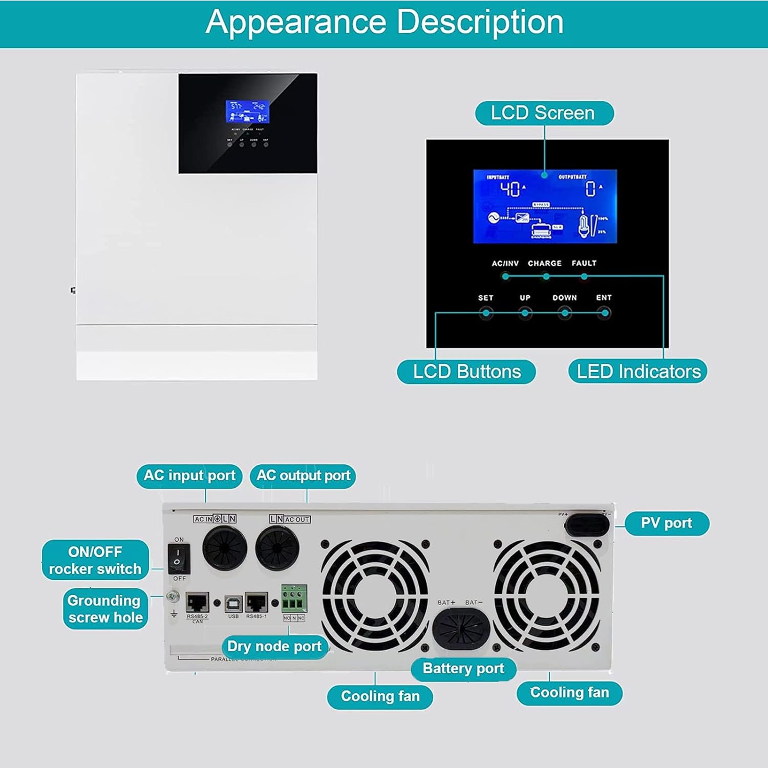
Figure 4: Detailed view of the inverter's front panel (LCD, buttons, indicators) and rear panel (AC input/output, PV port, battery port, dry node port, ON/OFF switch, grounding screw hole, cooling fans).
- LCD Screen: Displays real-time operational data and settings.
- LCD Buttons (SET, UP, DOWN, ENT): Used for navigation and configuration.
- LED Indicators (AC/INV, CHARGE, FAULT): Provide status feedback.
- AC Input Port: Connects to grid or generator AC power.
- AC Output Port: Connects to household appliances.
- PV Port: Connects to solar panels.
- Battery Port: Connects to the 48V battery bank.
- Dry Node Port: For communication or external control.
- ON/OFF Rocker Switch: Main power switch for the unit.
- Grounding Screw Hole: For safety grounding connection.
- Cooling Fans: Automatically activate to maintain optimal operating temperature.
4. Setup and Installation
Before Installation:
- Ensure the installation site is well-ventilated, dry, and free from flammable materials.
- Mount the inverter vertically on a sturdy surface, allowing adequate clearance for cooling.
- Verify that all components (solar panels, batteries, AC wiring) are rated appropriately for the inverter's specifications.
- Disconnect all power sources before making any electrical connections.
Wiring Diagram:

Figure 5: A complete off-grid system diagram illustrating how the inverter connects to solar panels, a generator, utility power, a battery bank, and various home appliances.
Connection Steps:
- Grounding: Connect the grounding screw hole on the inverter to a reliable earth ground.
- Battery Connection: Connect the 48V battery bank to the Battery Port. Ensure correct polarity (+ to + and - to -). Use appropriate gauge wiring and fuses/breakers.
- PV Connection: Connect the solar panels to the PV Port. Observe correct polarity and ensure the PV input voltage (Max 500VDC) and current (Max 80A) are within the inverter's limits.
- AC Input Connection: If using grid or generator power, connect the AC input source (110V/120V AC) to the AC Input Port. Install an appropriate circuit breaker.
- AC Output Connection: Connect your household appliances or load center to the AC Output Port. Install an appropriate circuit breaker.
- Power On: Once all connections are secure and verified, switch on the battery breaker, then the PV breaker (if applicable), and finally the inverter's ON/OFF rocker switch.
Note: This inverter does not support parallel operation or stacking.
5. Operating Instructions
The inverter's LCD screen and buttons allow for monitoring and configuration of various parameters.

Figure 6: Detailed view of the LCD screen, control buttons (SET, UP, DOWN, ENT), and LED indicators (AC/INV, CHARGE, FAULT).
LCD Display:
The LCD screen displays real-time information such as input voltage, output voltage, battery status, charging current, and operational mode. Use the UP and DOWN buttons to navigate through the display screens.
Configuring Settings:
Press the SET button to enter the settings menu. Use UP and DOWN to select a parameter, and ENT to confirm or modify. Refer to the detailed settings section in the full manual for specific parameter adjustments (e.g., battery type, charging current, output voltage range).
Charging Modes:
The inverter supports four distinct charging modes, which can be configured via the LCD panel:
- Only Solar: Prioritizes solar power for charging the battery.
- Mains Priority: Prioritizes utility/grid power for charging, using solar only when mains are unavailable.
- Solar Priority: Prioritizes solar power for charging, using mains only when solar is insufficient.
- Mains & Solar Hybrid: Utilizes both solar and mains power for charging, optimizing based on availability and load.

Figure 7: Visual representation of the four selectable charging modes for the inverter.
6. Maintenance
Regular maintenance ensures the longevity and optimal performance of your inverter.
- Cleaning: Periodically clean the exterior of the inverter with a dry cloth. Ensure ventilation openings are free from dust and debris. Do not use liquid cleaners.
- Connections: Annually check all electrical connections (battery, PV, AC input/output) for tightness and corrosion. Loose connections can cause overheating and damage.
- Battery Inspection: For lead-acid batteries, check electrolyte levels and terminal condition as per battery manufacturer guidelines. For lithium batteries, monitor their state of charge and health via the inverter's display or a dedicated battery management system.
- Environment: Ensure the operating environment remains within specified temperature and humidity ranges.
7. Troubleshooting
If you encounter issues with your inverter, refer to the following common troubleshooting steps. For persistent problems, contact customer support.
| Problem | Possible Cause | Solution |
|---|---|---|
| Inverter not turning on | No battery connection, low battery voltage, ON/OFF switch off | Check battery connections, ensure battery voltage is above minimum operating level, turn ON/OFF switch to ON. |
| No AC output | Overload, short circuit, inverter fault, battery low | Reduce load, check for short circuits, check fault codes on LCD, charge battery. |
| Battery not charging from PV | No solar input, PV polarity reversed, PV voltage too low/high, MPPT fault | Check solar panel connections and sunlight, verify PV polarity, ensure PV voltage is within range, check MPPT status on LCD. |
| Battery not charging from AC | No AC input, AC input breaker tripped, charger fault | Check AC input connection, reset AC input breaker, check charger status on LCD. |
| Fault indicator lit | Internal fault, over-temperature, over-voltage, etc. | Note the fault code on the LCD (if available), power cycle the unit, ensure proper ventilation. If persistent, contact support. |
8. Specifications
The following table outlines the technical specifications for the POWLAND 5000W Solar Inverter Charger.

Figure 8: Overview of key specifications for the POWLAND 5000W Solar Inverter Charger.
| Parameter | Value |
|---|---|
| Model | 5000W |
| Rated Power | 5000W |
| Input Voltage (Battery) | 48 VDC |
| Output Voltage (AC) | 110V / 120V AC |
| Wave Form | Pure Sine Wave |
| Frequency Range | 50Hz/60Hz (Auto sensing) |
| Max PV Input Voltage | 500 VDC |
| Max PV Charge Current | 80A |
| Max AC Charge Current | 63A |
| Product Dimensions | 14.88 x 11.02 x 4.06 inches |
| Item Weight | 28.2 pounds |
| Manufacturer | Easun Power |
9. Warranty and Support
For warranty information and technical support, please refer to the documentation provided with your purchase or contact POWLAND customer service directly. Warranty terms typically cover manufacturing defects for a specified period from the date of purchase.
When contacting support, please have your product model (5000W) and purchase details readily available.