1. Introduction
This manual provides essential information for the safe and effective operation of your SATMW RM409B Digital Multimeter. The RM409B is a 9999-count, auto/manual ranging digital multimeter designed for measuring AC/DC voltage, AC/DC current, resistance, capacitance, frequency, duty cycle, temperature, diode, and continuity. It features an analog bar graph for quick visual indication of measurements.
2. Safety Information
To ensure safe operation, please read and understand all safety warnings and operating instructions before using the multimeter. Failure to observe these warnings can result in severe injury or damage to the instrument.
- Always ensure the test leads are in good condition and properly connected before making any measurements.
- Do not apply voltage or current that exceeds the maximum specified limits for the multimeter.
- Exercise extreme caution when working with live circuits. High voltages can be dangerous.
- Never measure resistance, continuity, or diode on a live circuit. Ensure the circuit is de-energized and capacitors are discharged before testing.
- Replace batteries promptly when the low battery indicator appears to maintain measurement accuracy.
- Do not operate the multimeter if it appears damaged or if the battery cover is not properly closed.
- Refer to the specifications section for detailed measurement ranges and safety ratings.
3. Package Contents
Verify that all items are present and in good condition upon unpacking:
- SATMW RM409B Digital Multimeter
- Test Leads (Red and Black)
- Temperature Probe
- Storage Bag
- User Manual (this document)
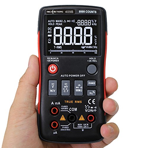
Image 3.1: Complete package contents of the RM409B Digital Multimeter, including the device, test leads, temperature probe, and storage bag.
4. Product Overview
4.1 Front Panel Layout

Image 4.1: Front panel of the RM409B Digital Multimeter, highlighting the LCD display, function buttons, and input terminals.
The front panel features a large LCD display with an analog bar graph, function selector buttons, and input jacks for test leads. Key buttons include Power, Function Selection (DC/AC, NCV, mV/°C/°F, 100MΩ, Range, Hz%), and Data Hold.
4.2 Side View
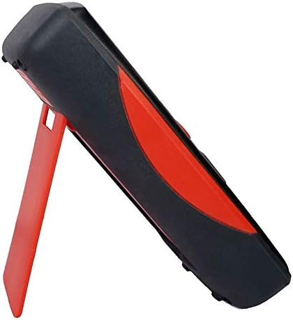
Image 4.2: Side view of the RM409B Digital Multimeter, showing the integrated kickstand in an extended position for hands-free operation.
The side of the multimeter features a robust, ergonomic design with a red accent. An integrated kickstand allows for convenient hands-free viewing during measurements.
4.3 Rear View

Image 4.3: Rear view of the RM409B Digital Multimeter, displaying the battery compartment cover and the kickstand.
The rear of the device includes the battery compartment and the pivot point for the kickstand. The battery compartment is secured with screws for safe battery access.
5. Setup
5.1 Battery Installation
The RM409B requires two 1.5V AA batteries (not included) for operation.
- Ensure the multimeter is powered off.
- Locate the battery compartment on the rear of the device.
- Unscrew the retaining screw(s) and remove the battery cover.
- Insert two 1.5V AA batteries, observing the correct polarity (+/-) as indicated inside the compartment.
- Replace the battery cover and secure it with the screw(s).
5.2 Test Lead Connection
Proper connection of test leads is crucial for accurate and safe measurements.
- Connect the red test lead to the VΩHz-||-+ input jack for voltage, resistance, frequency, capacitance, and diode measurements.
- Connect the black test lead to the COM (common) input jack for all measurements.
- For current measurements up to 999.9mA, connect the red test lead to the mA input jack.
- For current measurements up to 10A, connect the red test lead to the 10A input jack.
6. Operating Instructions
6.1 Power On/Off
Press and hold the red power button (labeled with a power symbol) for approximately 2 seconds to turn the multimeter on or off.
6.2 Function Selection
The RM409B operates in auto-ranging mode by default for most functions. To select specific functions or switch between AC/DC, press the corresponding function buttons:
- DC/ACA: Press to cycle between DC and AC current measurement modes.
- NCV: Non-Contact Voltage detection.
- mV/°C/°F: Cycle between millivolt, Celsius, and Fahrenheit temperature measurements.
- 100MΩ: For high resistance measurements.
- RANGE: Press to switch between auto-ranging and manual-ranging modes. In manual mode, press repeatedly to cycle through ranges.
- Hz%: Cycle between frequency and duty cycle measurements.
6.3 Measuring Voltage (AC/DC)
- Connect the red lead to the VΩHz-||-+ jack and the black lead to the COM jack.
- Power on the multimeter. It will typically default to auto-ranging voltage measurement.
- Press the DC/ACA button if you need to switch between AC and DC voltage modes.
- Connect the test leads in parallel to the circuit or component you wish to measure.
- Read the voltage value on the display.
6.4 Measuring Current (uA/mA/A)
Caution: Always connect the multimeter in series with the circuit when measuring current. Never connect it in parallel across a voltage source.
- For uA/mA: Connect the red lead to the mA jack and the black lead to the COM jack.
- For A: Connect the red lead to the 10A jack and the black lead to the COM jack.
- Power on the multimeter.
- Press the DC/ACA button to select AC or DC current mode.
- Open the circuit where you want to measure current and connect the multimeter in series.
- Read the current value on the display.
6.5 Measuring Resistance
Caution: Ensure the circuit is de-energized and all capacitors are discharged before measuring resistance.
- Connect the red lead to the VΩHz-||-+ jack and the black lead to the COM jack.
- Power on the multimeter.
- Connect the test leads across the component whose resistance you want to measure.
- Read the resistance value on the display.
6.6 Measuring Capacitance
Caution: Ensure the capacitor is fully discharged before measuring capacitance.
- Connect the red lead to the VΩHz-||-+ jack and the black lead to the COM jack.
- Power on the multimeter.
- Connect the test leads across the capacitor terminals.
- Read the capacitance value on the display.
6.7 Measuring Frequency/Duty Cycle
- Connect the red lead to the VΩHz-||-+ jack and the black lead to the COM jack.
- Power on the multimeter.
- Press the Hz% button to select frequency or duty cycle mode.
- Connect the test leads to the signal source.
- Read the frequency or duty cycle value on the display.
6.8 Diode Test
Caution: Ensure the circuit is de-energized before performing a diode test.
- Connect the red lead to the VΩHz-||-+ jack and the black lead to the COM jack.
- Power on the multimeter.
- Connect the red lead to the anode and the black lead to the cathode of the diode. A forward voltage drop will be displayed.
- Reverse the leads. The display should show 'OL' (Open Loop) for a good diode.
6.9 Continuity Test
Caution: Ensure the circuit is de-energized before performing a continuity test.
- Connect the red lead to the VΩHz-||-+ jack and the black lead to the COM jack.
- Power on the multimeter.
- Connect the test leads to the two points you want to test for continuity.
- If continuity exists (resistance below a certain threshold), the buzzer will sound, and the display will show the resistance value.
6.10 Temperature Measurement
- Connect the temperature probe to the appropriate input jacks (refer to the probe's markings, typically VΩHz-||-+ and COM).
- Power on the multimeter.
- Press the mV/°C/°F button to select Celsius or Fahrenheit.
- Place the tip of the temperature probe on or near the object whose temperature you wish to measure.
- Read the temperature value on the display.
6.11 Data Hold Function
Press the HOLD button to freeze the current reading on the display. Press it again to release the hold and resume live measurements.
6.12 Auto Power Off
The multimeter features an auto power-off function to conserve battery life. If no operation is performed for approximately 15 minutes, the device will automatically power off. Press any button or cycle the power to turn it back on.
7. Maintenance
Proper maintenance ensures the longevity and accuracy of your multimeter.
- Cleaning: Wipe the case with a damp cloth and mild detergent. Do not use abrasives or solvents.
- Battery Replacement: Replace batteries when the low battery indicator appears on the display. Refer to Section 5.1 for instructions.
- Fuse Replacement: If the current measurement function fails, the fuse may need replacement. This typically requires opening the back case. Refer to a qualified technician or the manufacturer for fuse specifications and replacement procedures.
- Storage: If the multimeter is not used for an extended period, remove the batteries to prevent leakage. Store in a cool, dry place away from direct sunlight.
8. Troubleshooting
Refer to the table below for common issues and their solutions.
| Problem | Possible Cause | Solution |
|---|---|---|
| No display when powered on | Dead or incorrectly installed batteries | Replace batteries, ensuring correct polarity. |
| "OL" displayed during measurement | Overload, open circuit, or out of range | Check connections, ensure circuit is closed, select a higher range if in manual mode. |
| Inaccurate readings | Low battery, incorrect function selected, poor test lead contact | Replace batteries, verify function, ensure good contact with test points. |
| Current measurement not working | Blown fuse | Replace the fuse (consult a technician). |
9. Specifications
Detailed technical specifications for the RM409B Digital Multimeter:
| Parameter | Specification |
|---|---|
| Model Number | RM409B |
| Display Type | Digital Display, 9999 Counts with Analog Bar Graph |
| Operating Mode | Auto/Manual Ranging |
| Sample Rate | 3 times per second |
| Operating Temperature | 0 - 40 °C (32 - 104 °F) |
| Operating Humidity | ≤75%RH |
| Storage Condition | -20 - 60 °C (-4 - 140 °F) |
| Storage Humidity | ≤80%RH |
| Power | 2 * 1.5V AA batteries (Not Included) |
| Measuring Voltage Range | 999.9mV / 9.999V / 99.99V / 999.9V |
| Measuring Current Range | 999.9uA / 99.99uA / 999.9mA / 10A |
| Measuring Resistance Range | 99.99Ω / 999.9Ω / 9.999kΩ / 99.99kΩ / 999.9KΩ / 9.999MΩ / 99.99MΩ |
| Measuring Capacitance Range | 9.99nF / 99.99nF / 999.9nF / 9.99uF / 99.99uF / 999.9uF / 9.999MF |
| Frequency Range | 99.99Hz / 999.9Hz / 9.999KHz / 99.99KHz / 999.9KHz / 5MHz |
| Duty Cycle | 1% - 99% |
| Measuring Temperature Range | -20 - 1000 °C / -4 - 1832 °F |
| Diode Test | Yes |
| Continuity | Yes |
10. Warranty and Support
For warranty information or technical support, please refer to the documentation provided with your purchase or contact SATMW customer service through their official channels. Keep your purchase receipt as proof of purchase for warranty claims.