1. Product Overview
The CNCTOPBAOS H100 2.2KW Variable Frequency Drive (VFD) Inverter is designed for precise speed control of 3-phase motors, commonly used in CNC routers, milling machines, and engraving machines. This VFD operates on a single-phase 220V input and provides a three-phase 220V output, with a power rating of 2.2KW (3HP) and an output frequency range of 0-1000 Hz.
Key features include no PG vector control and V/F speed control modes, 8-stage simple PLC function, multi-speed control, and PID control. It supports various frequency settings such as digital, analog, PID, and RS485 communication. The VFD also offers programmable I/O terminals for flexible operation and comprehensive fault protection functions.

2. Safety Instructions
Read all instructions carefully before installation, operation, or maintenance. Failure to follow these instructions may result in serious injury or equipment damage.
- Only qualified personnel should install, operate, and maintain this equipment.
- Ensure the power supply is disconnected before performing any wiring or maintenance.
- Properly ground the VFD inverter to prevent electrical shock.
- Do not touch electrical components immediately after power-off, as residual voltage may be present.
- Install the VFD in a clean, dry, and well-ventilated environment, away from direct sunlight, corrosive gases, and flammable materials.
- Verify that the input voltage matches the VFD's specifications (220V +/-15%).
- Do not operate the VFD with damaged cables or components.
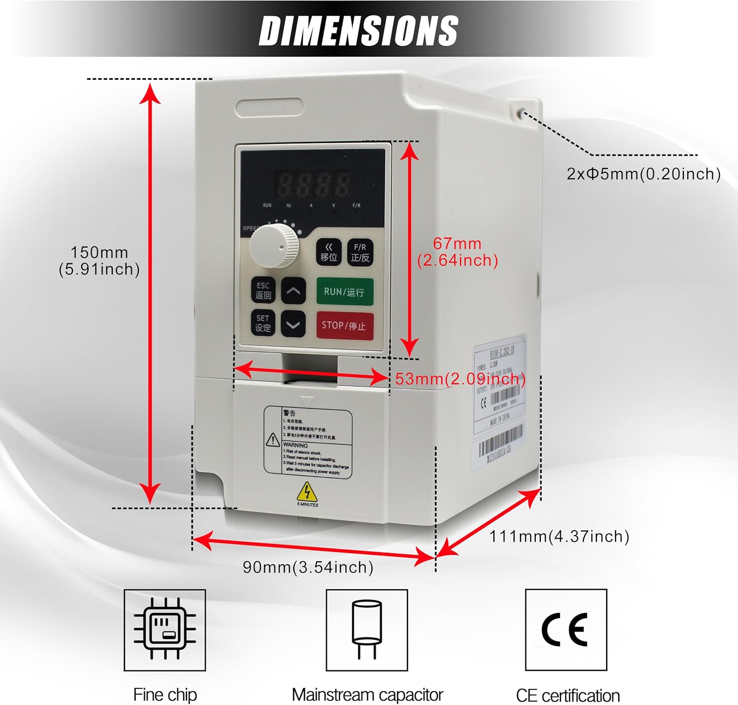
3. Product Components and Dimensions
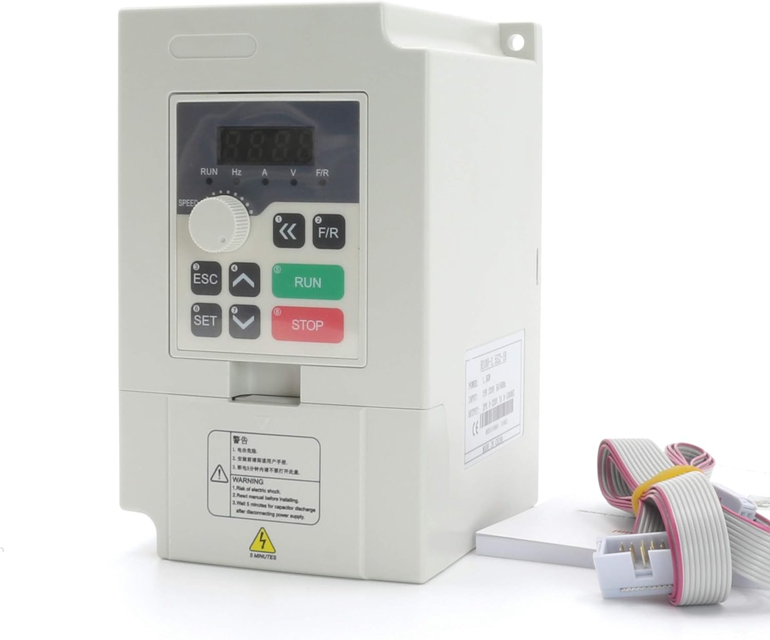
The H100 VFD Inverter features a compact design with an integrated control panel. Understanding its physical layout and dimensions is crucial for proper installation.

4. Installation
4.1 Unpacking and Inspection
Upon receiving the VFD, carefully unpack it and inspect for any signs of damage during transit. Ensure all components listed in the packing list are present. If any damage or missing parts are found, contact your supplier immediately.
4.2 Mounting
Mount the VFD vertically on a stable, non-flammable surface. Ensure adequate clearance around the unit for proper ventilation and heat dissipation. Avoid mounting in areas with excessive vibration, dust, or moisture.
4.3 Wiring
Proper wiring is critical for safe and reliable operation. Refer to the diagrams and terminal descriptions below for correct connections.
Main Circuit Terminals
The main circuit terminals are used for power input, motor output, and braking unit connections.
- L/N: Input power terminal. Connect to single-phase 220V power.
- U / V / W: Output terminals. Connect to the three-phase motor.
- DC+ / DC-: DC bus output terminals. Used for connecting an external brake unit or common DC bus system. (DC- is not provided for all models).
- DB: Brake output terminal. Connect a brake resistor between DB and DC+.
- PE: Earthing terminal. The inverter housing earthing terminal must be properly earthed.


Control Circuit Terminals and Jumper Functions
The VFD includes various control terminals and jumpers for configuring input/output signals and communication.
- J1: Selection of X1-X6 wiring mode (NPN/PNP). Factory setting: PNP.
- J2: Selection of AO output (VO/Voltage AO/Current). Factory setting: VO.
- J3: Selection of AI2 input (V/Voltage A/Current). Factory setting: A.
- J4: RS485 communication interface terminator enabled (ON/OFF). Factory setting: OFF.
- J5: Selection of X6 terminal function reuse (X6/Y1-PEO). Factory setting: X6.
Wiring Diagrams
Consult the following diagrams for detailed wiring instructions.


5. Operation
5.1 Control Panel Functions
The VFD features an intuitive control panel for easy operation and parameter adjustment.


- Run key: Initiates the run command.
- FOR/REV: Changes the running direction of the motor.
- (DISP) Shift key: Status monitor mode switch, parameter of third stage menu switch.
- Speed controller: Knob to switch between positive and negative during operation.
- ESC: Returns to the status of "ENTER".
- Set key (Enter): Enters menu, enters parameter, or confirms parameter data writing.
- Value change key: Adjusts parameters of function code, data, etc., for increase/decrease, revision, and selection of modes.
- Stop/Reset key: Stops command or abnormal reset command.
5.2 Basic Operation
- Power On: Ensure all wiring is correct and secure before applying power.
- Start Motor: Press the RUN key to start the motor.
- Adjust Speed: Use the speed controller knob or the value change keys to adjust the output frequency and motor speed.
- Change Direction: Press the FOR/REV key to change the motor's rotation direction.
- Stop Motor: Press the STOP/RESET key to stop the motor.
5.3 Parameter Settings
The VFD supports various methods for setting operational parameters:
- Digital Setting: Adjust parameters directly through the control panel.
- Analog Setting: Use an external analog signal (e.g., potentiometer) connected to AI terminals.
- PID Setting: Utilize the built-in PID control function for process control.
- RS485 Communication Setting: Control and monitor the VFD via RS485 communication.
6. Maintenance
Regular maintenance ensures the longevity and optimal performance of your VFD Inverter.
- Cleaning: Periodically clean the VFD's exterior and cooling fan to prevent dust accumulation, which can hinder heat dissipation. Use a soft, dry cloth. Do not use liquid cleaners.
- Inspection: Regularly inspect all wiring connections for tightness and signs of wear or damage. Check for any unusual noises or odors during operation.
- Environment: Ensure the operating environment remains within specified temperature and humidity ranges.
- Fan Check: Verify that the cooling fan operates freely and without obstruction.
7. Troubleshooting
The VFD is equipped with various fault protection functions. If an error occurs, the display will show a fault code. Refer to the VFD's detailed manual for specific fault code interpretations. Common issues and general solutions are listed below:
| Problem | Possible Cause | Solution |
|---|---|---|
| Motor does not start | Incorrect wiring, no power, emergency stop active, parameter error. | Check wiring, verify power supply, release emergency stop, check parameter settings. |
| Overcurrent fault | Motor overload, short circuit, acceleration time too short. | Reduce load, check motor and cables, increase acceleration time parameter. |
| Overvoltage fault | Input voltage too high, deceleration time too short, regenerative load. | Check input voltage, increase deceleration time, consider adding a brake resistor. |
| Undervoltage fault | Input voltage too low, power supply instability. | Check input voltage, ensure stable power supply. |
| Overheat fault | Poor ventilation, ambient temperature too high, cooling fan failure. | Improve ventilation, reduce ambient temperature, check cooling fan. |
For detailed fault codes and advanced troubleshooting, refer to the complete technical manual or contact customer support.
8. Specifications
The following table outlines the key technical specifications for the CNCTOPBAOS H100 2.2KW VFD Inverter:
| Parameter | Value |
|---|---|
| Brand | CNCTOPBAOS |
| Model Name | H100 |
| Power Source | AC |
| Wattage | 2200 watts |
| Input Voltage | 220 Volts (+/-15%) |
| Output Voltage | 220 Volts |
| Input Frequency | 50-60 Hz |
| Output Frequency | 0-1000 Hz |
| Input Phase | Single-Phase |
| Output Phase | Three-Phase |
| Current | 12.5A |
| Horsepower | 3HP |
| Manufacturer | Changzhou Rattm Motor Co.,Ltd |
9. Warranty and Support
For warranty information, technical support, or service inquiries, please refer to the product packaging or contact your authorized CNCTOPBAOS dealer or customer service representative. Keep your purchase receipt as proof of purchase for warranty claims.