
1. Product Overview
This DIY kit allows you to build a simple LED Flashing Circuit, also known as a FLIP FLOP or ASTABLE MULTIVIBRATOR. It utilizes two transistors to alternately flash two LEDs, operating within a voltage range of 3V to 9V. This kit is designed for educational purposes, providing hands-on experience with basic electronics.

Image 1.1: Assembled Simple LED Flash DIY Kit. This image shows the completed circuit board with all components soldered in place, including resistors, capacitors, transistors, LEDs, and the terminal block for power input.
2. Components List
Before beginning assembly, please verify that all components listed below are present in your kit. Refer to the image for visual identification of the components.
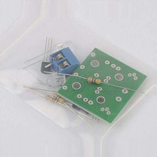
Image 2.1: Components of the Simple LED Flash DIY Kit. This image displays the individual electronic components included in the kit, such as resistors, capacitors, transistors, LEDs, the PCB, and the terminal block, typically provided in a clear plastic bag.
| Item Name | Specifications | Code | Quantity |
|---|---|---|---|
| Resistor | 470R | R1, R4 | 2 |
| Resistor | 10K | R2, R3 | 2 |
| Capacitance | 47uF/16V | C1, C2 | 2 |
| LED | Φ5mm | D1, D2 | 2 |
| Transistor | 9014 | Q1, Q2 | 2 |
| Terminal Block | 2-pin | J1 | 1 |
| PCB | YSG-1 | N/A | 1 |
3. Circuit Diagram and Operation Principle
The circuit diagram for the FLIP FLOP / ASTABLE MULTIVIBRATOR is fundamental to understanding its operation. While a visual diagram is not provided in this manual, the operational principle is detailed below.
Operation Principle:
The circuit relies on a slight difference in the gain (amplification ability) of the two transistors, Q1 and Q2. One transistor will inevitably turn on faster, initiating the flashing sequence.
- If Q1 turns on first, its collector voltage drops close to 0V, causing LED D1 to illuminate. Simultaneously, the positive lead of capacitor C1 will be near 0V, and its negative lead will also be near 0V. This applies 0V to the base of Q2, turning Q2 off, and thus LED D2 remains unilluminated.
- Capacitor C1 then gradually charges (in the opposite direction of its polarity) through resistor R2 (10kΩ). When the voltage at the base of Q2 reaches approximately 0.65V, Q2 begins to turn on.
- As Q2 turns on, the voltage at its collector decreases, causing the positive lead of capacitor C2 to drop. This in turn causes the negative lead of C2 to drop, reducing the voltage at the base of Q1. This action begins to turn Q1 off, and its collector voltage starts to rise.
- The rising collector voltage of Q1 further increases the voltage at the base of Q2, causing Q2 to turn on more strongly. This rapid, self-reinforcing process is known as regenerative action, where one transistor turning off causes the other to turn on. The two transistors quickly swap states.
- Consequently, the second LED (D2) illuminates, and the first LED (D1) turns off. This cycle then repeats, with C2 charging and eventually causing the state to flip back. The flashing frequency is determined by the values of capacitors C1, C2, and resistors R2, R3.
4. Assembly Instructions
Assembly requires basic soldering skills and tools (soldering iron, solder, wire cutters). Follow these steps carefully:
- Identify Components: Sort and identify all components using the provided components list and the PCB markings. Pay attention to resistor color codes and capacitor polarity.
- Solder Resistors: Start with the lowest profile components. Solder the four resistors (two 470R and two 10K) into their designated positions (R1, R2, R3, R4) on the PCB. Bend the leads, insert, and solder from the bottom side. Trim excess leads.
- Solder Transistors: Solder the two 9014 transistors (Q1, Q2). Ensure correct orientation; the flat side of the transistor should match the flat marking on the PCB silkscreen.
- Solder Capacitors: Solder the two 47uF/16V electrolytic capacitors (C1, C2). Observe polarity: The longer lead is positive (+), and the stripe on the capacitor body indicates the negative (-) lead. Match the positive lead to the '+' marking on the PCB.
- Solder LEDs: Solder the two LEDs (D1, D2). Observe polarity: The longer lead of the LED is the anode (+), and the shorter lead is the cathode (-). The flat edge on the LED's plastic casing also indicates the cathode. Match the anode to the '+' marking on the PCB.
- Solder Terminal Block: Solder the 2-pin terminal block (J1) into its position. This will be used for power input.
- Inspect Soldering: Carefully inspect all solder joints for cold joints, bridges, or poor connections. Ensure all components are securely attached and correctly oriented.
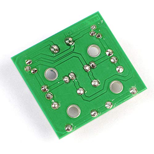
Image 4.1: Back of the PCB, showing solder points. This view is crucial for verifying proper soldering and lead trimming during assembly.
5. Operating Instructions
Once assembled, the circuit is ready for operation.
- Power Connection: Connect a DC power source (e.g., battery pack, regulated power supply) with a voltage between 3V and 9V to the terminal block. Ensure correct polarity: positive (+) to the '+' marked terminal and negative (-) to the '-' marked terminal.
- Observe Flashing: Upon applying power, the two LEDs (D1 and D2) should begin to flash alternately. The rate of flashing will depend on the values of the resistors and capacitors used in the circuit.
- Power Disconnection: To turn off the circuit, simply disconnect the power source.
6. Maintenance
This DIY kit requires minimal maintenance once assembled.
- Cleaning: If necessary, gently clean the PCB with a soft, dry cloth. Avoid using liquids or abrasive materials.
- Storage: Store the assembled circuit in a dry, cool environment away from direct sunlight and excessive dust.
- Component Check: Periodically inspect solder joints for any signs of cracking or corrosion, especially if the circuit is frequently handled or exposed to varying temperatures.
7. Troubleshooting
If the circuit does not function as expected, consider the following common issues:
- No LEDs Light Up:
- Check power supply: Ensure it is connected correctly (polarity) and provides 3V-9V.
- Check LED polarity: Verify LEDs are inserted with the correct orientation.
- Check solder joints: Look for cold joints (dull, grainy appearance) or unsoldered pins. Re-solder if necessary.
- Check for short circuits: Ensure no solder bridges are connecting adjacent traces or component leads.
- Only One LED Lights Up (or stays on):
- Check transistor orientation: Ensure both Q1 and Q2 are inserted with the correct flat-side orientation.
- Check capacitor polarity: Verify C1 and C2 are inserted with the correct positive/negative orientation.
- Check resistor values: Confirm R2 and R3 are 10K, and R1 and R4 are 470R.
- Inspect solder joints around the non-flashing LED's path and its associated transistor/capacitor.
- Irregular Flashing / Not Flashing as Expected:
- Verify capacitor values: Ensure C1 and C2 are 47uF. Incorrect values will alter the flash rate.
- Check for loose connections or intermittent solder joints.
8. Specifications
| Feature | Detail |
|---|---|
| Suite Name | Flashing / Blinking Light |
| Suite Type | YSG-1 |
| Operating Voltage | 3V ~ 9V DC |
| Dimensions (PCB) | 30mm x 28mm |
| Circuit Type | Astable Multivibrator (Flip-Flop) |
| Manufacturer | Lufasa |
| ASIN | B0924V9HST |
9. Warranty and Support
As a DIY kit, this product is intended for educational and hobbyist use. Due to the nature of assembly by the end-user, specific warranties on the assembled product may not apply. However, components are typically guaranteed to be free from manufacturing defects upon receipt.
For support regarding missing or defective components, please contact your retailer or the manufacturer, Lufasa, through their official channels. Please provide your purchase details and a description of the issue.