1. Introduction
Thank you for choosing the American Volt 14-15 Inch Electric Radiator Cooling Fan Kit. This kit provides an efficient cooling solution for your vehicle's radiator, engine, or transmission cooler. It includes a high-performance electric fan, a comprehensive wiring kit, and a temperature-activated thermostat switch. Please read this manual thoroughly before installation and operation to ensure proper function and safety.
2. Safety Information
- Always disconnect the vehicle's battery before performing any electrical work to prevent electrical shock or short circuits.
- Wear appropriate personal protective equipment, including safety glasses and gloves, during installation.
- Ensure all wiring connections are secure and properly insulated to prevent fire hazards or system malfunctions.
- Do not operate the fan with damaged blades or housing.
- Keep hands and loose clothing away from moving fan blades.
- Consult a qualified automotive technician if you are unsure about any part of the installation process.
3. Package Contents
Verify that all components listed below are present in your package:
- 14-15 Inch Electric Radiator Cooling Fan
- Universal 5-pin 40A Relay Switch Harness Kit
- Dual Pin Electric Cooling Fan Thermostat Switch with Push-in Fin Probe
- Mounting Bracket Feet
- Cooler Fin Tie Strap Kit (Mounting Rods, Foam Pads, Springs, Clips)
- Installation Instructions and Wiring Diagram (included with wiring kit)

Image 1: The 14-15 inch electric radiator cooling fan, showing its multi-blade design and housing.
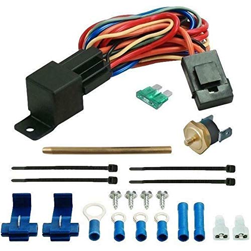
Image 2: Components of the universal wiring kit, including the relay, fuse, and various wires.
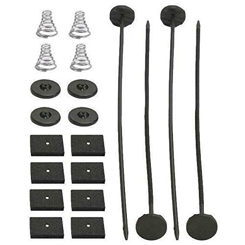
Image 3: The complete set of mounting hardware, including springs, foam pads, and mounting rods.
4. Product Features
- Universal Compatibility: Designed for various automotive applications, suitable for 14-15 inch radiator sizes.
- High Performance Fan: Features an upgraded 130-watt motor, drawing 11 amps and producing over 2723 CFM for effective cooling.
- Reversible Airflow: Configured as an air puller by default, but can be reversed to an air pusher configuration.
- Slim Design: Measures 15" x 14" x 3.2" thickness at the center and a slim 1.8" at the edge for versatile mounting.
- Complete Wiring Kit: Includes a 5-pin 40A relay switch harness kit with 14AWG wire, suitable for 1-2 cooling fans or 12-volt accessories.
- Integrated Protection: Features a 30A in-line fuse for circuit protection.
- Thermostat Control: Dual pin electric cooling fan thermostat switch with a solid brass push-in fin probe.
- Pre-set Temperature: Activates the fan at 180°F (82°C) and deactivates at 165°F (74°C).
- Versatile Probe: The probe can be cut to size and pins to radiator, engine, or transmission cooler fins to measure liquid temperatures (oil, water, coolant).
5. Installation
5.1. Fan Mounting
The fan can be mounted as an air puller (behind the radiator, pulling air through) or an air pusher (in front of the radiator, pushing air through). The fan is configured as an air puller by default. To reverse airflow, simply reverse the polarity of the fan motor wires (swap positive and negative connections).
- Position the fan against the radiator core.
- Insert the mounting rods through the fan's mounting feet and then through the radiator fins.
- Place the foam pads on the rods against the radiator to protect the fins.
- Slide the springs onto the rods from the opposite side of the radiator.
- Secure the rods with the plastic clips, ensuring a snug fit without overtightening, which could damage the radiator fins.
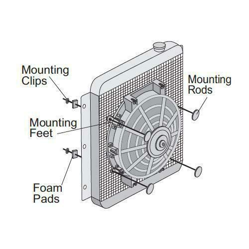
Image 4: Diagram illustrating the fan mounting process on a radiator, showing the placement of mounting feet, rods, and clips.
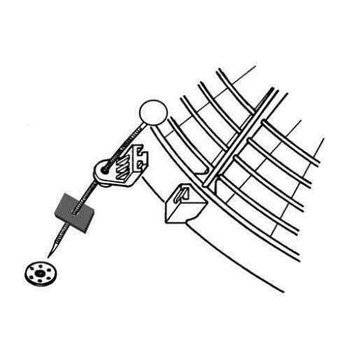
Image 5: Close-up view of how the mounting clip, spring, foam pad, and rod secure the fan to the radiator fins.
5.2. Thermostat Installation
The thermostat uses a push-in fin probe to sense temperature.
- Locate a suitable area on the radiator fins, engine, or transmission cooler where the probe can be securely inserted and accurately measure liquid temperature.
- Carefully push the brass probe between the fins until it is firmly seated. The probe can be cut to a shorter length if necessary for specific applications.
- Ensure the probe makes good contact with the fins for accurate temperature readings.
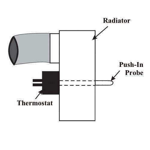
Image 6: Diagram showing the push-in probe of the thermostat inserted into the radiator fins.
5.3. Wiring Kit Installation
The wiring kit includes a 5-pin 40A relay and is designed for 12-volt systems. Refer to the wiring diagram included with your kit for detailed connections. A general overview is provided below:
- Power Source: Connect the main power wire (typically red, 14AWG) with the in-line 30A fuse to a constant 12V power source from the battery.
- Ground: Connect the ground wire (typically black) to a reliable chassis ground point.
- Fan Connection: Connect the fan motor wires to the relay output wires. Ensure correct polarity for desired airflow (reverse for pusher configuration).
- Thermostat Connection: Connect the thermostat switch to the relay trigger wire. When the thermostat reaches its turn-on temperature, it will complete the circuit to activate the relay.
- Ignition/Accessory Power: Connect the ignition/accessory wire (if present) to a switched 12V source that is active when the ignition is on.
- A/C Override/Manual Switch: The harness may include a wire for A/C override or a manual toggle switch. Connect this as per the included wiring diagram if desired. This allows the fan to be activated when the A/C is on or manually.
Secure all wiring to prevent chafing, heat damage, or interference with moving parts. Use appropriate connectors and heat shrink tubing for durable connections.
6. Operation
Once properly installed, the electric cooling fan system operates automatically based on the thermostat's temperature readings.
- When the temperature sensed by the probe reaches 180°F (82°C), the thermostat will activate the relay, turning on the electric fan.
- The fan will continue to run until the temperature drops to 165°F (74°C), at which point the thermostat will deactivate the relay, turning off the fan.
- If an A/C override or manual switch is connected, the fan can also be activated independently of the thermostat's temperature setting.
Monitor your vehicle's temperature gauge after installation to ensure the system is functioning correctly and maintaining optimal operating temperatures.
7. Maintenance
Regular maintenance helps ensure the longevity and efficient operation of your cooling fan kit.
- Inspect Fan Blades: Periodically check the fan blades for any cracks, damage, or debris accumulation. Clean blades gently if necessary.
- Check Wiring: Inspect all wiring connections for corrosion, fraying, or loose terminals. Ensure all insulation is intact.
- Verify Mounting: Confirm that the fan and thermostat probe remain securely mounted and have not loosened due to vehicle vibrations.
- Clean Radiator Fins: Ensure the radiator fins are free from dirt, leaves, and other obstructions that could impede airflow.
- Test Thermostat: Occasionally verify the thermostat's function by observing the fan's activation and deactivation at the specified temperatures.
8. Troubleshooting
| Problem | Possible Cause | Solution |
|---|---|---|
| Fan does not turn on | Blown fuse Loose wiring connection Faulty thermostat Faulty relay Incorrect wiring | Check and replace 30A in-line fuse Inspect all connections, ensure they are secure Test thermostat for continuity Test relay function Review wiring diagram and correct connections |
| Fan runs continuously | Stuck thermostat (closed circuit) Faulty relay (stuck closed) Incorrect wiring (constant power to fan) | Test thermostat, replace if faulty Test relay, replace if faulty Review wiring diagram and correct connections |
| Fan is noisy or vibrates excessively | Damaged fan blades Loose mounting Debris in fan housing | Inspect blades for damage, replace fan if necessary Tighten mounting rods and clips Clear any obstructions from fan housing |
| Engine overheats despite fan operation | Insufficient airflow (fan direction) Radiator blockage Low coolant level Other cooling system issues | Verify fan is pulling/pushing air in the correct direction Clean radiator fins thoroughly Check and top up coolant Consult a mechanic for further diagnosis of the cooling system |
9. Specifications
- Brand: American Volt
- Operating Voltage: 12 Volts
- Wattage: 130 Watts
- Current Draw: 11 Amps (Fan Motor)
- Airflow: Over 2723 CFM
- Fan Dimensions: 15" x 14" x 3.2" (center thickness), 1.8" (edge thickness)
- Thermostat Turn-On Temperature: 180°F (82°C)
- Thermostat Turn-Off Temperature: 165°F (74°C)
- Wiring Kit Relay: 5-pin, 40A
- Wiring Kit Fuse: 30A In-line
- Wiring Gauge: 14 AWG
- Material: Plastic (Fan Housing), Brass (Thermostat Probe)
10. Warranty & Support
For warranty information, technical support, or assistance with your American Volt Electric Radiator Cooling Fan Kit, please refer to the documentation provided at the time of purchase or contact American Volt customer service directly. Keep your proof of purchase for warranty claims.


