1. Introduction
The Coolwell AS7341 Spectral Color Sensor Module is a high-precision visible spectrum sensor designed for various applications requiring accurate color measurement and identification. It integrates an AS7341 chip, offering multiple visible spectrum channels, a near-infrared channel, and a no-filter channel. This module is compatible with popular development platforms such as Raspberry Pi, Arduino, and STM32, utilizing an I2C control interface for communication.
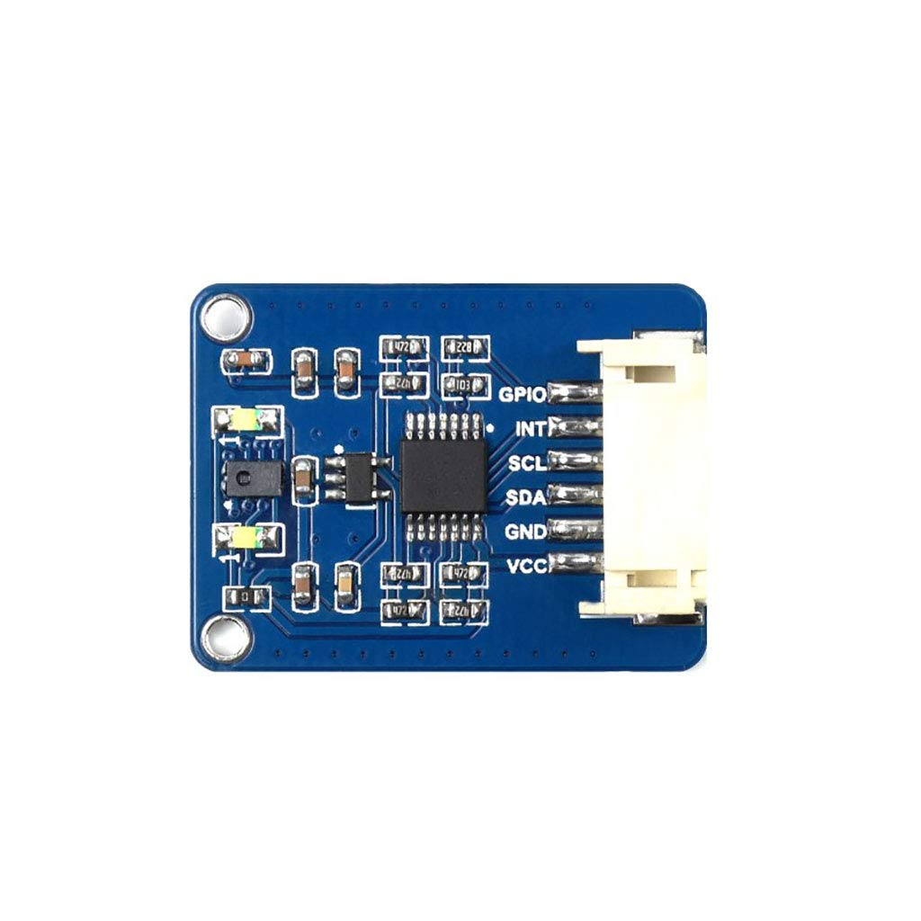
Figure 1: Top view of the AS7341 Spectral Color Sensor Module.
2. Features
- Incorporates AS7341 chip with 8x visible spectrum channels, 1x near-infrared channel, and 1x no-filter channel.
- Embedded 6x independent 16-bit Analog-to-Digital Converters (ADC) for parallel data processing.
- Dedicated channel for detecting ambient light flicker at specific frequencies.
- Two high-brightness LEDs for use as fill light in low-light environments.
- Interrupt pin to output real-time ADC operating status.
- Spectrum interrupt detection with programmable high/low thresholds.
- General Purpose Input/Output (GPIO) pin.
- Onboard voltage translator, compatible with 3.3V and 5V operating voltages.
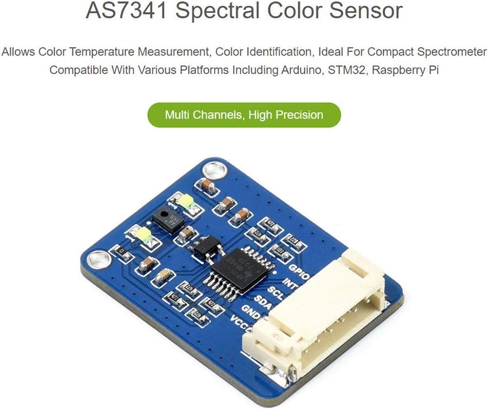
Figure 2: AS7341 module highlighting its multi-channel and high-precision capabilities.
3. Setup and Hardware Connection
3.1 Pinout Description
The AS7341 module communicates via an I2C interface. Below is a description of the module's pins:

Figure 3: AS7341 module pinout and I2C control interface.
| Pin | Description |
|---|---|
| VCC | 3.3V/5V power input |
| GND | Ground |
| SDA | Connects to MCU I2C data pin |
| SCL | Connects to MCU I2C clock pin |
| INT | Interrupt output |
| GPIO | General purpose input/output |
3.2 Connecting with Raspberry Pi
Follow the diagram below to connect the AS7341 module to a Raspberry Pi board. Ensure correct pin alignment for VCC, GND, SDA, SCL, INT, and GPIO.

Figure 4: Connection diagram for Raspberry Pi (top) and Arduino (bottom).
- Connect the module's VCC to the Raspberry Pi's 3.3V or 5V power pin (depending on your setup).
- Connect the module's GND to the Raspberry Pi's Ground pin.
- Connect the module's SDA to the Raspberry Pi's SDA (I2C Data) pin.
- Connect the module's SCL to the Raspberry Pi's SCL (I2C Clock) pin.
- Connect the module's INT to an available GPIO pin on the Raspberry Pi for interrupt functionality (optional).
- Connect the module's GPIO to another available GPIO pin on the Raspberry Pi for general purpose I/O (optional).
3.3 Connecting with Arduino Board
Refer to the diagram in Figure 4 for connecting the AS7341 module to an Arduino board. Pay close attention to the I2C pins (SDA, SCL) which may vary by Arduino model.
- Connect the module's VCC to the Arduino's 3.3V or 5V power pin.
- Connect the module's GND to the Arduino's Ground pin.
- Connect the module's SDA to the Arduino's SDA (Analog 4 on Uno, Digital 20 on Mega).
- Connect the module's SCL to the Arduino's SCL (Analog 5 on Uno, Digital 21 on Mega).
- Connect the module's INT to an available digital pin on the Arduino for interrupt functionality (optional).
- Connect the module's GPIO to another available digital pin on the Arduino for general purpose I/O (optional).
4. Operating Instructions
The AS7341 module operates via the I2C communication protocol. To use the sensor, you will need to write or adapt code for your chosen microcontroller (Raspberry Pi, Arduino, STM32) to communicate with the AS7341 chip.
4.1 I2C Communication
The AS7341 acts as an I2C slave device. Your microcontroller will act as the I2C master. You will need to:
- Initialize the I2C bus on your microcontroller.
- Address the AS7341 module using its I2C slave address (refer to the AS7341 datasheet for the default address).
- Write to specific registers to configure the sensor, such as enabling channels, setting gain, integration time, and interrupt thresholds.
- Read from specific registers to obtain spectral data from the 8 visible, 1 near-infrared, and 1 no-filter channels.
- Process the 16-bit ADC values to interpret the spectral data.
4.2 Software Libraries and Examples
It is recommended to use existing software libraries provided by the manufacturer or community for Raspberry Pi, Arduino, or STM32 to simplify interaction with the AS7341. These libraries typically handle the low-level I2C communication and provide functions for easy configuration and data reading.
Refer to the development resources and examples that come with the module for specific programming guidance.
5. Maintenance
- Handling: Handle the module with care to avoid physical damage to components or solder joints.
- Environment: Operate the module within its specified temperature and humidity ranges. Avoid exposure to extreme temperatures, moisture, or corrosive substances.
- Cleaning: If necessary, gently clean the module with a soft, dry cloth. Do not use liquids or abrasive cleaners. Ensure the sensor's optical window remains clear and free of dust or smudges for accurate readings.
- Power Supply: Always ensure a stable and correct voltage power supply (3.3V/5V) to prevent damage to the module.
6. Troubleshooting
- Module Not Detected (I2C):
- Verify all wiring connections (VCC, GND, SDA, SCL) are secure and correct.
- Ensure the power supply voltage is within the 3.3V-5V range.
- Check if the I2C address used in your code matches the AS7341's default address.
- Confirm that the I2C bus is enabled and properly initialized on your microcontroller.
- Incorrect Readings:
- Ensure the sensor's optical window is clean and unobstructed.
- Check ambient lighting conditions; strong or fluctuating light sources can affect readings.
- Verify sensor configuration parameters in your code (gain, integration time).
- Ensure the object being measured is within the sensor's optimal detection range.
- Module Not Powering On:
- Double-check power connections (VCC and GND).
- Test the power supply to ensure it is providing the correct voltage.
7. Specifications
| Feature | Detail |
|---|---|
| Sensor Chip | AS7341 |
| Communication Bus | I2C |
| Operating Voltage | 3.3V / 5V |
| Logical Voltage | 3.3V / 5V |
| Dimensions | 30.5 x 23 mm |
| Mounting Hole Size | 2.0 mm |
| Compatible Devices | Raspberry Pi, Arduino, STM32 |
| Item Model Number | AS7341 |
| UPC | 735584848907 |
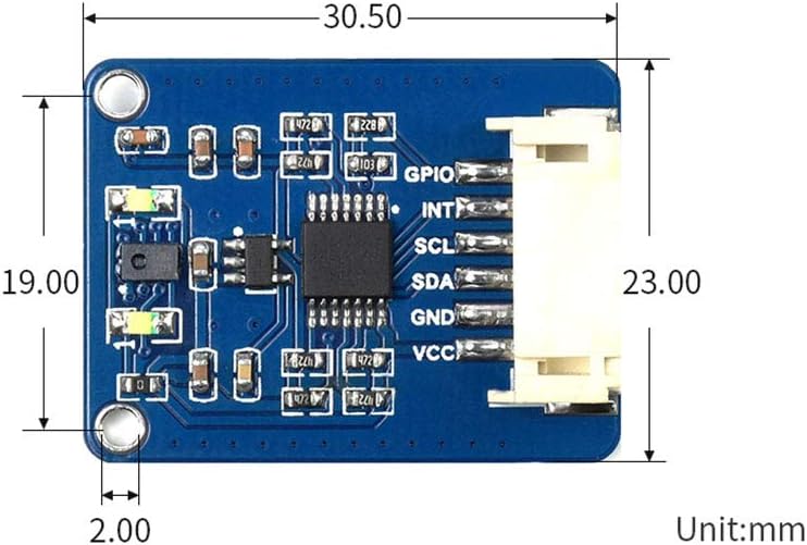
Figure 5: Dimensions of the AS7341 module.
8. Warranty and Support
For warranty information, technical support, or further inquiries regarding the Coolwell AS7341 Spectral Color Sensor Module, please refer to the official Coolwell website or contact their customer service directly. Keep your purchase receipt for any warranty claims.