
1. Introduction
The SENRISE 3D Touch Auto Leveling Sensor Kit is designed to enhance the accuracy and reliability of 3D printing by providing automatic bed leveling capabilities. This sensor utilizes the Hall effect to precisely detect the print surface, compensating for unevenness in the print bed and ensuring consistent first layer adhesion. This manual provides detailed instructions for installation, operation, and maintenance of your 3D Touch sensor.
2. Package Contents
Before proceeding with installation, please verify that all components are present in your package.
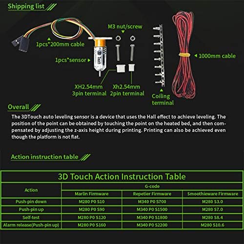
Figure 2.1: Package Contents Diagram
This image illustrates the various components included in the SENRISE 3D Touch Auto Leveling Sensor Kit. It shows the main sensor unit, two different lengths of connection cables (200mm and 1000mm), mounting hardware (M3 nuts and screws), and terminal connectors (XH2.54mm 3-pin and 2-pin, along with a coiling terminal).
- 1x 3D Touch Sensor
- 1x 200mm Connection Cable
- 1x 1000mm Connection Cable
- M3 Nuts and Screws (for mounting)
- XH2.54mm 3-pin Terminal
- XH2.54mm 2-pin Terminal
- Coiling Terminal
3. Product Overview
The 3D Touch sensor is a compact and precise device designed for automatic bed leveling. It operates by deploying a probe to touch the print surface, registering the Z-axis position, and then retracting. This process allows the 3D printer's firmware to compensate for any inconsistencies in the print bed's flatness, leading to improved print quality and reduced print failures.

Figure 3.1: 3D Touch Sensor Unit
This image provides a detailed view of the 3D Touch sensor itself, highlighting its small form factor and the probe mechanism. The sensor is white with "3D Touch" branding visible.
4. Setup and Installation
4.1 Mounting the Sensor
Mount the 3D Touch sensor securely to your 3D printer's print head assembly. Ensure that the sensor's probe can extend below the nozzle when deployed and retract fully without interfering with the nozzle or printed parts. Use the provided M3 screws and nuts for attachment. The exact mounting location will depend on your specific printer model.

Figure 4.1: Sensor Mounted on a 3D Printer
This image demonstrates the typical mounting position of the 3D Touch sensor on a 3D printer's extruder assembly. The sensor is shown adjacent to the hotend, with its probe aligned to measure the print bed's surface.
4.2 Wiring Connections
Connect the 3D Touch sensor to your 3D printer's control board. The sensor typically requires a 3-pin connection for power and signal, and a 2-pin connection for the Z-min endstop. Refer to your printer's mainboard documentation for specific pin assignments. Use the provided cables and terminals.
- 3-pin connector: Typically for VCC (5V), GND, and Signal (control pin).
- 2-pin connector: Typically for Z-min endstop (connected to the Z-min endstop pins on the mainboard).
Note: Incorrect wiring can damage the sensor or your printer's mainboard. If unsure, consult your printer's manufacturer or an experienced technician.
4.3 Firmware Configuration
After physical installation, your 3D printer's firmware must be configured to recognize and utilize the 3D Touch sensor. This usually involves modifying the Marlin, Repetier, or Smoothieware firmware settings. Key steps include:
- Enable
AUTO_BED_LEVELING_BILINEARor similar auto-leveling feature. - Define the probe offsets (
NOZZLE_TO_PROBE_OFFSET) relative to the nozzle. - Configure the Z-min endstop to use the probe instead of a physical switch.
- Upload the modified firmware to your 3D printer.
Refer to the documentation for your specific firmware version for detailed instructions.
5. Operating Instructions
Once installed and configured, the 3D Touch sensor automates the bed leveling process. The following G-code commands are commonly used for interaction and calibration.
5.1 Basic G-code Commands
| Action | Marlin Firmware | Repetier Firmware | Smoothieware Firmware |
|---|---|---|---|
| Push-pin down | M280 P0 S10 | M340 P0 S700 | M280 S3.0 |
| Push-pin up | M280 P0 S90 | M340 P0 S1500 | M280 S7.0 |
| Self-test | M280 P0 S120 | M340 P0 S1800 | M280 S8.4 |
| Alarm release (Push-pin up) | M280 P0 S160 | M340 P0 S2200 | M280 S10.6 |
These commands can be sent via your printer's control interface (e.g., OctoPrint, Pronterface, or directly from the printer's LCD menu if supported) to manually control the sensor for testing or specific operations.
5.2 Auto Bed Leveling Process
To initiate the automatic bed leveling process, include the G28 (Home All Axes) and G29 (Auto Bed Leveling) commands in your G-code start script before each print. The printer will then:
- Home all axes (X, Y, Z).
- Deploy the 3D Touch probe.
- Probe multiple points across the print bed.
- Create a mesh or matrix of bed height deviations.
- Retract the probe.
- Apply real-time Z-axis compensation during printing based on the measured mesh.
6. Maintenance
The 3D Touch sensor is designed for low maintenance. However, periodic checks can ensure optimal performance:
- Probe Cleanliness: Ensure the probe tip is free from debris, filament residue, or dust. A dirty probe can lead to inaccurate readings.
- Mounting Security: Periodically check that the sensor is securely mounted and has not loosened due to printer vibrations.
- Cable Integrity: Inspect the wiring for any signs of wear, fraying, or damage. Ensure connections are firm.
- Probe Movement: Manually deploy and retract the probe (using G-code commands if necessary) to ensure it moves freely without obstruction.
7. Troubleshooting
7.1 Sensor Not Deploying/Retracting
- Check Wiring: Verify all connections are correct and secure, especially the 3-pin power/signal cable.
- Power Supply: Ensure the printer's power supply is adequate and stable.
- Firmware: Confirm that the firmware is correctly configured for the 3D Touch sensor and that the appropriate G-code commands are being sent.
- Obstruction: Check for any physical obstructions preventing the probe from moving.
7.2 Inaccurate Leveling/First Layer Issues
- Probe Offset: Re-calibrate the
NOZZLE_TO_PROBE_OFFSETin your firmware. This is critical for accurate Z-height. - Probe Cleanliness: Clean the probe tip as described in the Maintenance section.
- Mounting Stability: Ensure the sensor is rigidly mounted and does not wobble.
- Bed Surface: Ensure the print bed surface is clean and free of inconsistencies that might interfere with probing.
- G-code Order: Verify that
G28andG29are correctly placed in your start G-code.
7.3 Sensor LED Behavior
The 3D Touch sensor typically has an LED indicator. Refer to the sensor's specific documentation for detailed LED status meanings. Common states include:
- Solid Blue/Red: Sensor powered on, probe retracted.
- Flashing: Probe deployed or error state.
8. Specifications
| Feature | Specification |
|---|---|
| Brand | SENRISE |
| Model | 3D Touch Auto Leveling Sensor Kit |
| Voltage | 5 Volts |
| Material | Metal, PC |
| Probe Type | Hall Effect Sensor |
| Cable Lengths | 200mm, 1000mm |
9. Warranty and Support
9.1 Warranty Information
This product is covered by a standard manufacturer's warranty against defects in materials and workmanship. Please retain your proof of purchase for warranty claims. The warranty period typically begins from the date of purchase. For specific warranty terms and conditions, please refer to the seller's policy or contact SENRISE customer support.
Note: Damage caused by improper installation, misuse, or unauthorized modifications is not covered under warranty.
9.2 Customer Support
For technical assistance, troubleshooting, or inquiries regarding your SENRISE 3D Touch Auto Leveling Sensor Kit, please contact our customer support team. You can typically find support contact information on the product packaging or the seller's website.
- Online Resources: Check the SENRISE official website or relevant community forums for FAQs and additional guides.
- Contact Seller: For purchase-related issues, contact the seller directly through the platform where the product was purchased.