Introduction
This manual provides detailed instructions for the Q-BAIHE AD7606 Multi-Channel AD Data Acquisition Module. The AD7606 is a 16-bit, 8-channel synchronous sampling analog-to-digital converter (ADC) module designed for high-performance data acquisition applications. It features a sampling frequency of 200KHz across all channels and supports various oversampling modes.
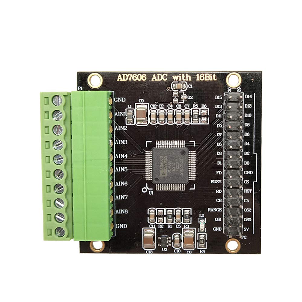
Figure 1: Overview of the AD7606 Multi-Channel AD Data Acquisition Module.
Setup
Follow these steps to set up your AD7606 module:
- Power Supply: Connect a stable DC5V power supply to the module. Ensure the polarity is correct. The module's maximum current consumption is 20mA.
- Communication Interface: The module supports SPI serial communication and 8-channel data parallel communication. Connect your microcontroller (e.g., STM32F103X-M3) to the appropriate data interface pins. The module control signal level is 3.3V.
- Analog Input Connection: Connect your analog signals to the 8 independent input channels via the 3.81-8PIN terminal. The input voltage range can be configured for ±5V or ±10V via software. The input impedance is 1M ohm.
- Reference Voltage: The module includes an internal 2.5V reference. An external reference can be used by soldering an SOT-23 package external input reference.
- Module Interface: The module features a 3.81-10PIN socket and an XH2.54 double row pin data interface for connections.

Figure 2: Labeled diagram showing key components and connection points on the AD7606 module, including AD acquisition channels, reference selection, and serial/parallel data ports.

Figure 3: Pin mapping table illustrating connections between STM32 microcontroller pins and AD7606 module pins for proper integration.
Operating Instructions
The AD7606 module is designed for high-speed, high-resolution data acquisition.
- Resolution: The module provides 16-bit analog-to-digital conversion, offering high precision for your measurements.
- Sampling Rate: All 8 channels can be sampled synchronously at a rate of up to 200KSPS (kilo-samples per second).
- Oversampling Modes: To improve signal-to-noise ratio and resolution, the module supports six oversampling modes: 2x, 4x, 8x, 16x, 32x, and 64x. These modes are software configurable.
- Software Routines: Example routines are provided for the STM32F103RBT6 microcontroller, facilitating integration and development on platforms such as the STM32F103X-M3.

Figure 4: Functional block diagram of the AD7606, illustrating the internal architecture including analog inputs, multiplexer, ADC core, digital filter, and serial/parallel interfaces.
Maintenance
To ensure the longevity and optimal performance of your AD7606 module, observe the following maintenance guidelines:
- Environmental Conditions: Operate the module within its specified temperature and humidity ranges. Avoid exposure to extreme temperatures, moisture, or corrosive environments.
- Cleaning: If cleaning is necessary, use a soft, dry cloth. Do not use liquid cleaners or solvents, as these can damage the electronic components.
- Handling: Handle the module with care to prevent physical damage. Avoid static discharge by using appropriate ESD precautions when handling.
- Power Off: Always disconnect the power supply before making or changing any connections to the module.
Troubleshooting
If you encounter issues with your AD7606 module, consider the following troubleshooting steps:
- No Power: Verify that the DC5V power supply is correctly connected and providing the specified voltage. Check for loose connections.
- Incorrect Readings:
- Ensure analog input signals are within the configured ±5V or ±10V range.
- Check all analog input connections for proper seating and continuity.
- Verify the software configuration for input range and oversampling modes matches your application.
- Confirm the reference voltage is stable and correctly configured (internal or external).
- Communication Errors:
- Check SPI or parallel data connections between the module and your microcontroller.
- Verify the communication protocol implementation in your software matches the module's requirements.
- Ensure the control signal levels (3.3V) are correct.
- Module Not Responding: Disconnect power, wait a few seconds, and reconnect. If the issue persists, re-check all wiring and software initialization.
Specifications
| Feature | Specification |
|---|---|
| Module Model | AD7606 Analog-to-Digital Conversion Module |
| Module Power Supply | DC5V |
| Module Current | 20mA (MAX) |
| Communication Protocol | SPI serial, 8-channel data parallel |
| Control Signal Level | 3.3V |
| Input Voltage Range | ±5V or ±10V (software switching) |
| Input Impedance | 1M ohm |
| ADC Resolution | 16 bits |
| Sampling Rate | 200KSPS (all channels) |
| Number of Input Channels | 8 independent (synchronous sampling) |
| Reference Voltage | Internal 2.5V (external input option available) |
| Oversampling Modes | 2x, 4x, 8x, 16x, 32x, 64x |
| Module Input Interface | 3.81-8PIN terminal |
| Module Interface Type | 3.81-10PIN socket, XH2.54 double row pin data interface |
| Module Dimensions | 50mm x 50mm x 12mm |
| Module Weight | 23g |
| Provided Routines | STM32F103RBT6 |
| Example Platform | STM32F103X-M3 |
| Manufacturer Part Number | KWKJ-AD7606 |

Figure 5: Physical dimensions of the AD7606 module, showing its 50mm by 50mm footprint.
Warranty and Support
Information regarding the warranty period and specific support contacts for the Q-BAIHE AD7606 module is not provided in the product details. For warranty claims or technical assistance, please refer to the vendor or retailer from whom the product was purchased.