1. Introduction
This manual provides essential information for the safe and effective operation of your AIOMEST AI-39C Digital Multimeter. Please read this manual thoroughly before use and retain it for future reference. The AI-39C is a True RMS (TRMS) digital multimeter designed for precise measurement of AC/DC voltage, AC/DC current, resistance, continuity, capacitance, frequency, diode, NCV, and temperature.
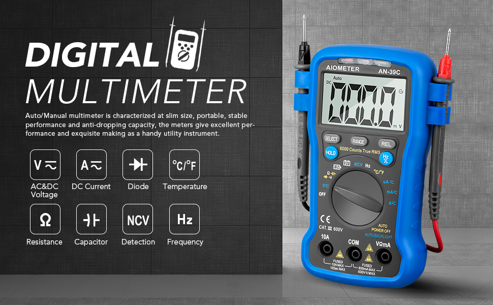
Image 1.1: AIOMEST Digital Multimeter overview, emphasizing its robust and portable design.
2. Safety Information
Always adhere to basic safety precautions when using this multimeter to prevent electric shock, injury, or damage to the meter or equipment under test.
- Do not exceed the maximum input values specified for each range.
- Exercise extreme caution when working with voltages above 30V AC RMS, 42V peak, or 60V DC. These voltages pose a shock hazard.
- Before measuring current, ensure the circuit is de-energized and the meter is connected in series.
- Before measuring resistance, continuity, or diode, ensure the circuit is de-energized and all capacitors are discharged.
- Inspect test leads for damaged insulation or exposed metal before use. Replace if damaged.
- Do not operate the meter if it appears damaged or if the case is open.
- Remove test leads from the circuit before changing functions.
- Replace the battery when the low battery indicator appears to ensure accurate readings.
3. Package Contents
Verify that all items listed below are included in your package:
- AIOMEST AI-39C Digital Multimeter
- Test Leads (Red and Black)
- Thermocouple (for temperature measurement)
- Alligator Clip Test Lead
- Wrist/Hanging Strap
- Magnetic Base
- 9V Battery
- User Manual
- Multimeter Storage Case

Image 3.1: Complete package contents of the AIOMEST AI-39C Digital Multimeter.
4. Product Overview
The AIOMEST AI-39C Digital Multimeter features a robust design with multiple functionalities for various electrical measurements. It includes a large LCD display for clear readings and an automatic backlight for visibility in low-light conditions.
4.1 Key Features
- Auto-Ranging: Automatically selects the correct measurement range.
- True RMS: Provides accurate readings for non-sinusoidal AC waveforms.
- NCV Detection: Non-Contact Voltage detection for safety.
- Data Hold: Locks the displayed measurement value.
- Automatic Backlight: Adjusts based on ambient brightness.
- Automatic Power Off: Conserves battery after 15 minutes of inactivity.
- Multiple Mounting Options: Includes a folding kickstand, magnet, and wrist/hanging strap for hands-free operation.

Image 4.1: Visual representation of the AI-39C's main features.
4.2 Multimeter Components
Familiarize yourself with the different parts of your multimeter:

Image 4.2: Labeled diagram of the AIOMEST AI-39C Digital Multimeter.
- NCV Detection Area: Used for non-contact voltage detection.
- CDS Sensor: Controls automatic LCD backlight.
- LCD Display: 6000 counts digit, full function symbol display.
- Range Key: Switches between manual and automatic range modes.
- Select Key: Long press to switch manual/automatic power off.
- REL Key: Activates relative measurement mode.
- Hold Key: Locks the display value.
- Hertz / % Key: For frequency or duty cycle measurements.
- Rotary Switch: Used to select functions and ranges.
- 10A Jack / COM Jack / VΩmA Jack: Input terminals for test leads.

Image 4.3: Close-up of the LCD display with automatic backlight.
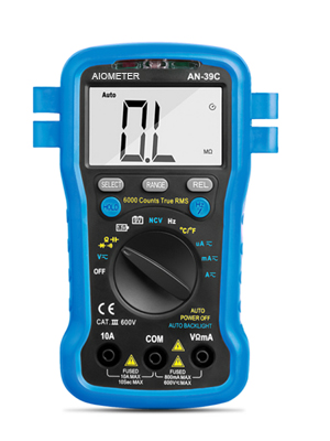
Image 4.4: Multimeter with kickstand for convenient viewing.
5. Setup
5.1 Battery Installation
The multimeter requires a 9V battery (included). To install or replace the battery:
- Ensure the multimeter is turned OFF and test leads are disconnected.
- Locate the battery compartment cover on the back of the meter.
- Use a screwdriver to loosen the screw(s) and remove the cover.
- Connect the 9V battery to the battery clip, observing correct polarity.
- Place the battery into the compartment and replace the cover, securing it with the screw(s).
5.2 Connecting Test Leads
Always connect the black test lead to the COM (common) jack. Connect the red test lead to the appropriate input jack based on the measurement function:
- For Voltage, Resistance, Diode, Continuity, Capacitance, Frequency, and Temperature measurements, connect the red lead to the VΩmA jack.
- For Current measurements up to 10A, connect the red lead to the 10A jack.
6. Operating Instructions
Turn the rotary switch to the desired function. The meter will typically auto-range. Use the 'RANGE' button to switch to manual ranging if needed. Use the 'SELECT' button to toggle between different sub-functions within a rotary switch position (e.g., AC/DC voltage, diode/continuity).

Image 6.1: Multimeter in use, measuring a circuit board.
6.1 AC/DC Voltage Measurement
- Set the rotary switch to the V~ (AC Voltage) or V- (DC Voltage) position.
- Connect the red test lead to the VΩmA jack and the black test lead to the COM jack.
- Connect the test probes in parallel across the circuit or component to be measured.
- Read the voltage value on the LCD display.
6.2 AC/DC Current Measurement
Caution: Never connect the meter in parallel with a voltage source when measuring current. This can blow the fuse or damage the meter.
- Turn off power to the circuit.
- Set the rotary switch to the A~ (AC Current) or A- (DC Current) position. For currents up to 600mA, use the VΩmA jack. For currents up to 10A, use the 10A jack.
- Break the circuit and connect the test probes in series with the load.
- Restore power to the circuit.
- Read the current value on the LCD display.
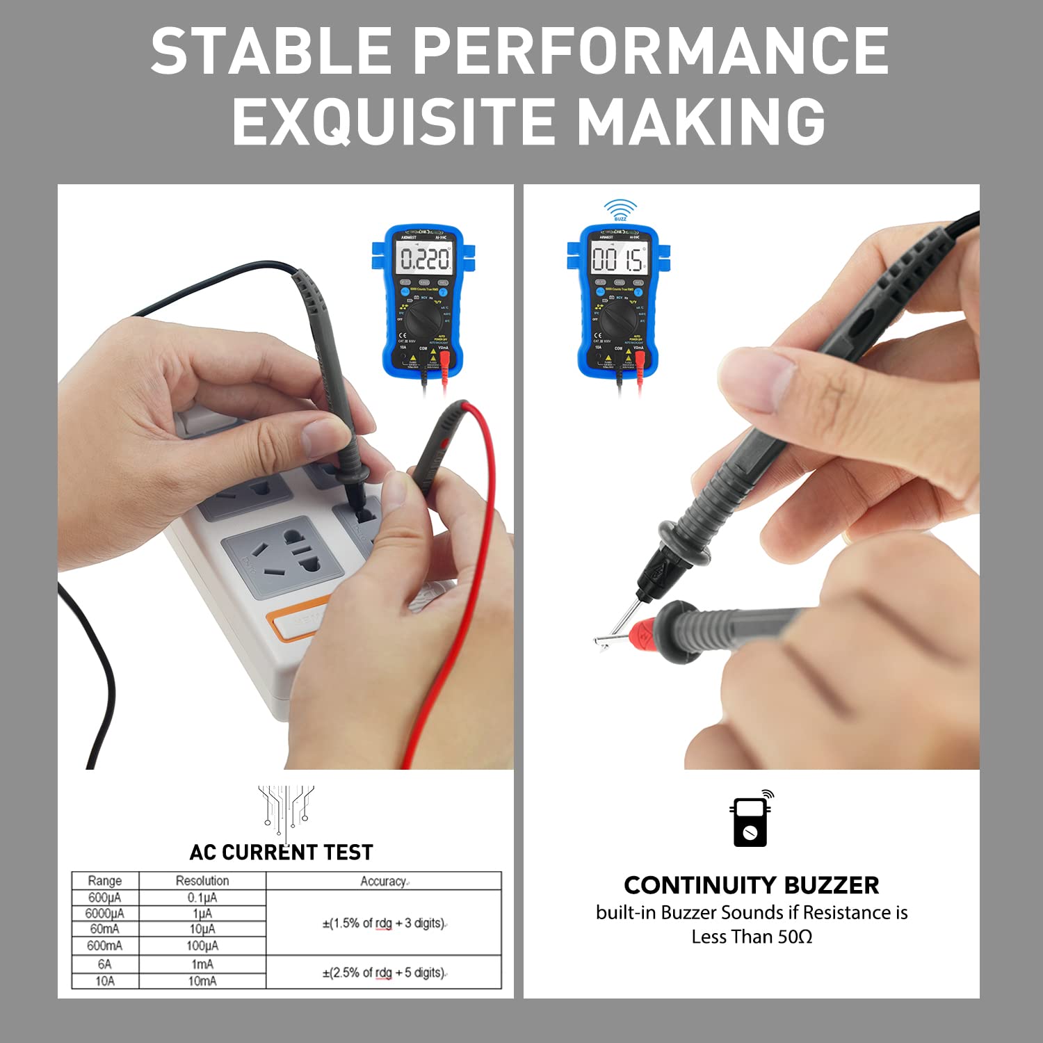
Image 6.2: AC Current Test table and Continuity Buzzer details.
6.3 Resistance Measurement
- Ensure the circuit is de-energized and all capacitors are discharged.
- Set the rotary switch to the Ω (Resistance) position.
- Connect the red test lead to the VΩmA jack and the black test lead to the COM jack.
- Connect the test probes across the component to be measured.
- Read the resistance value on the LCD display.
6.4 Continuity Test
- Ensure the circuit is de-energized.
- Set the rotary switch to the Ω position and press 'SELECT' until the continuity symbol (speaker icon) appears.
- Connect the test probes across the circuit or component.
- If continuity exists (resistance less than approximately 50Ω), the buzzer will sound.
6.5 Diode Test
- Ensure the circuit is de-energized.
- Set the rotary switch to the Ω position and press 'SELECT' until the diode symbol appears.
- Connect the red test probe to the anode and the black test probe to the cathode of the diode.
- The display will show the forward voltage drop. Reverse the probes; the display should show 'OL' (Open Line) for a good diode.
6.6 Capacitance Measurement
- Ensure the capacitor is fully discharged before testing.
- Set the rotary switch to the CAP position.
- Connect the test probes across the capacitor.
- Read the capacitance value on the LCD display.
6.7 Frequency/Duty Cycle Measurement
- Set the rotary switch to the Hz/% position.
- Connect the test probes across the signal source.
- Read the frequency (Hz) or duty cycle (%) on the LCD display.
6.8 NCV (Non-Contact Voltage) Detection
- Set the rotary switch to the NCV position.
- Move the NCV detection area of the meter close to the conductor suspected of having AC voltage.
- The meter will emit an audible beep and the NCV indicator light will flash if AC voltage is detected.
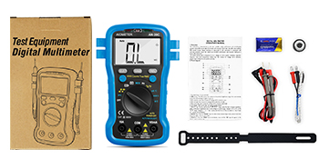
Image 6.3: Using the NCV function near a circuit breaker panel.
6.9 Temperature Measurement
- Set the rotary switch to the °C/°F position.
- Connect the thermocouple to the VΩmA and COM jacks, observing polarity.
- Place the thermocouple probe on or near the object whose temperature is to be measured.
- Read the temperature value in Celsius or Fahrenheit on the LCD display.
6.10 Battery Test (1.5V/9V)
- Set the rotary switch to the 1.5V/9V battery test position.
- Connect the red test lead to the positive terminal and the black test lead to the negative terminal of the battery.
- Read the battery voltage on the LCD display.
6.11 Data Hold Function
Press the HOLD button to freeze the current reading on the display. Press it again to release the hold function.
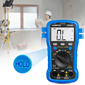
Image 6.4: The 'HOLD' function button.
6.12 Relative Measurement (REL)
Press the REL button to store the current reading as a reference value. Subsequent measurements will be displayed as the difference from this reference. Press again to exit relative mode.
7. Maintenance
7.1 Cleaning
Wipe the meter with a damp cloth and mild detergent. Do not use abrasives or solvents.
7.2 Automatic Power Off
The meter automatically powers off after approximately 15 minutes of inactivity to conserve battery life. To disable or enable this feature, long press the 'SELECT' key while turning the meter on.
7.3 Automatic Backlight
The LCD backlight automatically activates in low-light conditions and turns off in bright environments. This feature is controlled by the CDS sensor.
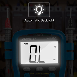
Image 7.1: Automatic backlight feature in action.
7.4 Battery Replacement
When the low battery indicator appears on the display, replace the 9V battery as described in Section 5.1.
8. Troubleshooting
- No display or faint display: Check battery installation. Replace battery if low battery indicator is on or if display is dim.
- 'OL' displayed: Indicates an open circuit, out-of-range measurement, or incorrect function selection.
- Incorrect readings: Ensure test leads are properly connected, the correct function is selected, and the circuit is de-energized for resistance/continuity/diode tests.
- No continuity beep: Check if the continuity function is selected. Ensure resistance is below 50Ω.
9. Specifications
| Parameter | Value |
|---|---|
| Brand | AIOMEST |
| Model Number | AI-39C |
| Display | 6000 Counts, Digital LCD |
| AC Voltage Range | Up to 600V |
| DC Voltage Range | Up to 600V |
| AC Current Range | Up to 10A |
| DC Current Range | Up to 10A |
| Resistance Range | Up to 60 MΩ |
| Capacitance Range | Yes (Specific range not provided, auto-ranging) |
| Frequency/Duty Cycle | Yes |
| Temperature Measurement | Yes (°C/°F) |
| Continuity Test | Yes (Audible buzzer) |
| Diode Test | Yes |
| NCV Detection | Yes |
| Battery Test | 1.5V/9V |
| Power Source | 9V Battery |
| Item Weight | 470 Grams |
| Dimensions (Package) | 18.2 x 11.5 x 5.8 cm |
| UPC | 774298493195 |
10. Warranty and Support
The AIOMEST AI-39C Digital Multimeter comes with a 12-month quality warranty. In case of quality issues, options for replacement or refund are available. For technical support or warranty claims, please contact AIOMEST customer service through your purchase platform or the contact information provided with your product.