
ATNSINC CP2102 USB 2.0 to TTL
ATNSINC CP2102 USB to TTL Serial Adapter User Manual
Model: CP2102 USB 2.0 to TTL
1. Introduction
The ATNSINC CP2102 USB to TTL Serial Adapter provides a reliable solution for connecting microcontrollers (MCUs) and other serial devices to your computer via a standard USB port. This module features the stable CP2102 chipset, offering dual 3.3V and 5V power outputs, and supports a wide range of operating systems. It is designed for electronic projects requiring UART communication.
2. Package Contents
Each package includes:
- 3 x CP2102 USB to TTL 5-Pin UART Modules
- 3 x Jumper Wires (20cm)
3. Key Features
- Stable and reliable CP2102 chipset.
- Supports STC single-chip microcomputers with 3.3V and 5V output.
- Compatible with Windows (98SE, 2000, XP, Vista, 7, 8, Server 2003/200), Mac OS (9, X), and Linux (2.40 or later).
- Baud rates from 300 bps to 1.5 Mbps, with support up to 115200 bps.
- Standard USB Type-A male connector and 5-pin TTL interface.
- Pinout includes 3.3V, RST, TXD, RXD, GND, and 5V.
- Integrated resettable fuse for protection against accidental short-circuits.
- Indicator LEDs for power, data reception (RXD), and data transmission (TXD).
4. Setup Guide
4.1 Driver Installation
The CP2102 chipset requires specific drivers for your operating system. These drivers are typically available from the Silicon Labs website. Search for 'CP2102 USB to UART Bridge VCP Drivers' and download the appropriate version for your system (Windows, Mac, Linux). Install the drivers before connecting the module to your computer.
4.2 Physical Connection
Connect the USB Type-A male connector of the module to an available USB port on your computer. Use the included jumper wires to connect the module's TTL pins to your target device (e.g., microcontroller).
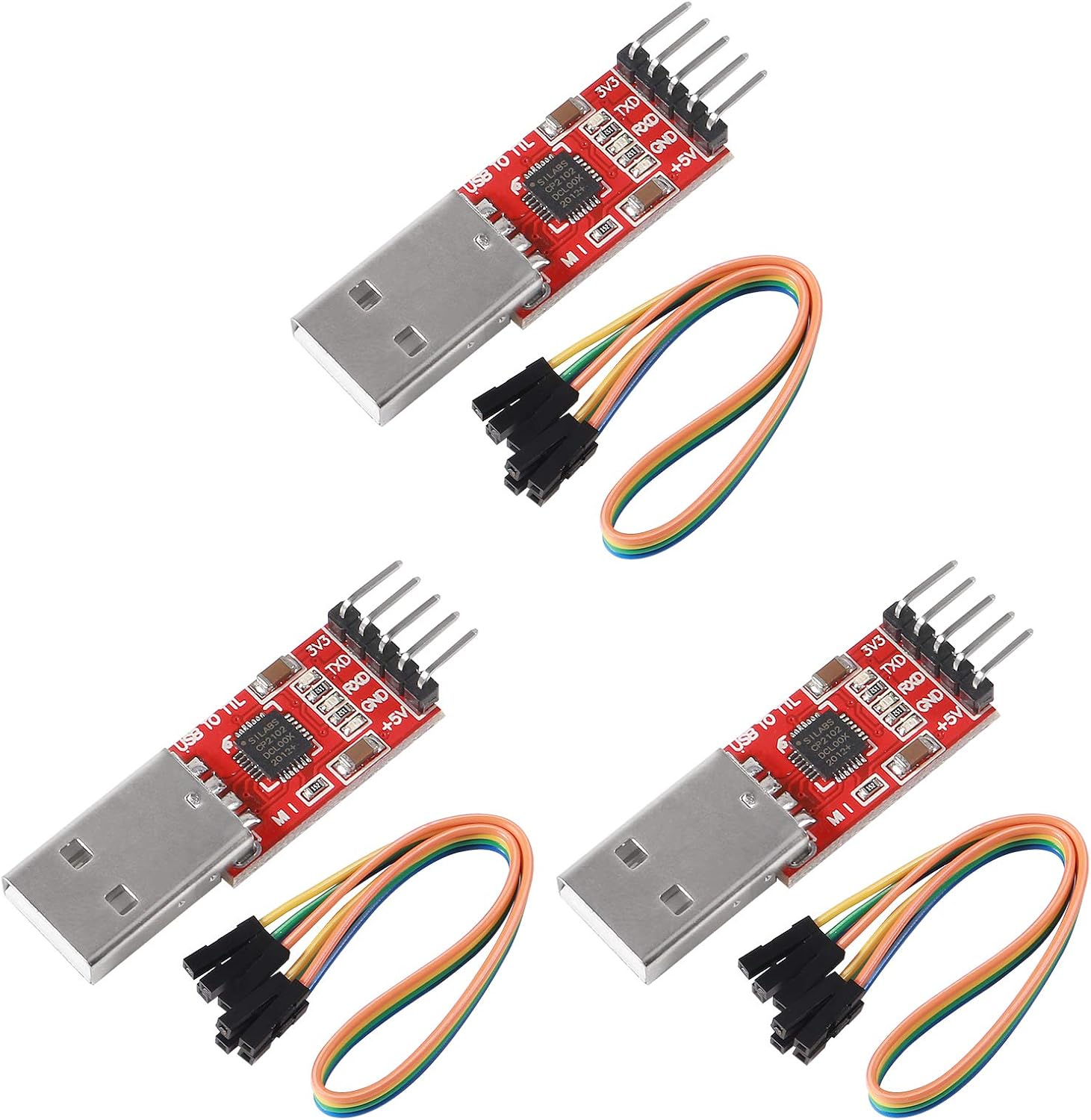
Figure 1: Overview of the ATNSINC CP2102 USB to TTL Serial Adapter, showing the USB Type-A male connector on one end and the 5-pin header on the other. The red PCB board is visible, along with the CP2102 chip.
4.3 Pinout Diagram
The 5-pin header provides the following connections:
- +5V: 5V power output.
- GND: Ground connection.
- TXD: Transmit Data (connect to the RXD pin of your target device).
- RXD: Receive Data (connect to the TXD pin of your target device).
- 3V3: 3.3V power output.
- RST: Reset pin (functionality may vary or not be used in all applications).

Figure 2: A detailed view of the CP2102 module's circuit board, highlighting the CP2102 integrated circuit, resistors, capacitors, and the clearly labeled 5-pin header: +5V, GND, TXD, RXD, 3V3.

Figure 3: This image provides four close-up perspectives: the CP2102 chip with its markings, the USB Type-A connector, the 5-pin header with voltage and data labels, and another view of the USB connector.
5. Operating Instructions
5.1 Power Selection
The module provides both 3.3V and 5V power outputs. Ensure you connect the appropriate voltage pin (+5V or 3V3) to your target device based on its operating voltage requirements. Incorrect voltage can damage your device.
5.2 Data Communication
Once connected and drivers are installed, your computer will recognize the module as a virtual COM port. Use a serial terminal program (e.g., PuTTY, Tera Term, Arduino Serial Monitor) to communicate with your target device. Configure the serial port settings (baud rate, data bits, stop bits, parity) to match those of your target device.
5.3 Indicator LEDs
- Power LED: Illuminates when the module receives power from the USB port.
- TXD LED: Flashes when data is being transmitted from the module to the target device.
- RXD LED: Flashes when data is being received by the module from the target device.
Note: At higher baud rates, the TXD/RXD LEDs may appear dimmer due to rapid flashing.
6. Maintenance
- Keep the module clean and dry. Avoid exposing it to extreme temperatures or humidity.
- Handle with care to prevent damage to the pins or components.
- The integrated resettable fuse protects against accidental short circuits. If a short occurs, disconnect the module, resolve the issue, and reconnect. The fuse will reset automatically.
7. Troubleshooting
7.1 Module Not Recognized
- Ensure CP2102 drivers are correctly installed. Verify installation in your operating system's Device Manager (Windows) or equivalent.
- Try a different USB port or computer.
- Check for conflicting drivers or devices. If the device is recognized with an incorrect ID (e.g., 'VeriFone USB to UART Bridge'), reinstalling official Silicon Labs drivers may resolve this.
7.2 No Communication
- Verify the TXD and RXD connections are correctly crossed (module TXD to device RXD, module RXD to device TXD).
- Confirm the baud rate, data bits, stop bits, and parity settings in your serial terminal match your target device.
- Ensure the target device is powered correctly (3.3V or 5V from the module, or external power).
- Check for loose jumper wire connections.
7.3 Device Not Powering On
- Ensure the +5V or 3V3 pin is correctly connected to your device's power input.
- Verify the GND connection.
- Check if the USB port is providing sufficient power.
7.4 LEDs Not Functioning
- If the Power LED is off, check the USB connection and try another port.
- If TXD/RXD LEDs are not flashing during communication, verify data flow and connections.
8. Specifications
| Feature | Detail |
|---|---|
| Chipset | CP2102 |
| Interface | USB 2.0 to TTL 5-Pin UART |
| Power Output | Dual 3.3V and 5V |
| Baud Rates | 300 bps to 1.5 Mbps (up to 115200 bps recommended) |
| Operating System Support | Windows (98SE, 2000, XP, Vista, 7, 8, Server 2003/200), Mac OS (9, X), Linux (2.40 or later) |
| Connector Type | USB Type A |
| Input Voltage | 5 Volts (from USB) |
| Current Rating | 1.5 Amps (max) |
| Dimensions (L x W x H) | 40mm x 10mm x 2.5mm (approx. module only) |
| Item Weight | 0.02 Kilograms |

Figure 4: An image illustrating the physical dimensions of the CP2102 module (approximately 40mm length, 10mm width) and the included 20cm long jumper wires, which are essential for connecting the module to other devices.
9. Warranty Information
This product comes with a standard manufacturer's warranty. Please refer to the seller's return policy or contact ATNSINC customer support for specific warranty details and duration.
10. Customer Support
For technical assistance or further inquiries, please contact ATNSINC customer support through the platform where the product was purchased.
Ask a question about this manual
Ask about setup, troubleshooting, compatibility, parts, safety, or missing instructions. Manuals+ will review the question and use this page’s manual context to help answer it.