
1. Introduction
This manual provides comprehensive instructions for the installation, operation, and maintenance of the Olideauto Automatic Dual Door Operator, Model Olide-120B. This system is designed to automate the opening and closing of two swing doors simultaneously, enhancing accessibility for all users, including those with disabilities.
Please read this manual thoroughly before installation and operation to ensure correct usage and to prevent potential hazards.
2. Safety Information
WARNING:
- Always ensure the power supply is disconnected before performing any installation, maintenance, or troubleshooting.
- Installation and adjustments must be carried out according to the instructions in this manual.
- Do not use the product beyond the stipulated voltage or frequency.
- Do not install in environments with excessive vibration or corrosive gases.
- Do not disassemble the unit. Refer to qualified personnel for repairs.
- The system includes a safety feature that automatically re-opens the door if an object is detected in the closing path. However, always exercise caution when the door is in motion.
3. Product Components
The Olideauto Automatic Dual Door Operator system includes the following main components:
- Two (2) Olide-120B Automatic Door Operators
- Two (2) Wireless & Wired Handicap Push Buttons
- One (1) Receiver for wireless communication
- One (1) Handheld Programmer
- Power cables and connection wires
- Mounting hardware (screws, brackets, etc.)
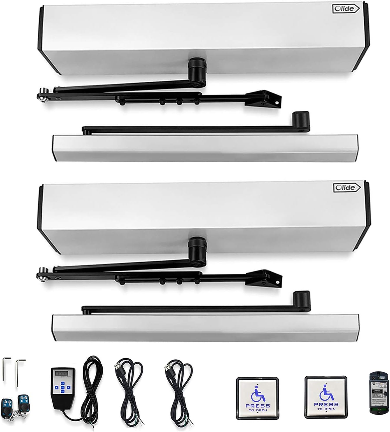
Image 3.1: Overview of the Olideauto Automatic Dual Door Operator system components, including two door operators, two handicap push buttons, a receiver, a handheld programmer, and associated cables and tools.

Image 3.2: Detailed view of the square 4.5-inch stainless steel wireless and wired handicap push switch, highlighting its dimensions and 2.4G wireless communication technology.

Image 3.3: Close-up of the Olide-510F Wireless Receive Controller, showing its learn button, adjustable settings for 'keep open' or 'auto close', buzzer control, and 2.4GHz radio frequency for high sensitivity and stability.
4. Specifications
| Parameter | Value |
|---|---|
| Model | Olide-120B |
| Application | One-way inswing or outswing open, single leaf and double leaf standard doors |
| Voltage | 110-220 VAC +/-10% |
| Motor | DC 24V brushless motor |
| Power Consumption | 50W |
| Opening Time (90 degrees) | 3-7 seconds |
| Hold Open Time | 1-30 seconds (Adjustable, can be set to remain open) |
| Max. Door Frame Depth (with push arm) | 200mm / 7.87 inches |
| Door Width (Max.) | 1200mm / 47.2 inches |
| Door Width (Min.) | 660mm / 26 inches |
| Max. Opening Angle | 120 degrees |
| Max. Door Weight (each panel) | 264 lbs (120 kg) |
| Environment Temperature | -20°C to 50°C (-4°F to 122°F) |
| Operation Noise | Less than 55db |
| Opener Size (L x W x H) | 21.45" x 3.35" x 3.74" (545mm x 85mm x 95mm) |
| Opener Weight | 44.0 lbs (20 kg) |
| Installation Type | Screw-In |
| Material | Aluminum |
| Batteries (included) | 4 x 12V Alkaline batteries |
| UPC | 759838851376 |

Image 4.1: Dimensional drawing of the Olideauto Automatic Door Operator, showing length, width, and height measurements in both inches and millimeters.
5. Setup and Installation
Proper installation is crucial for the safe and efficient operation of the Olideauto Automatic Dual Door Operator. It is recommended that installation be performed by qualified personnel.
5.1 Mounting the Operators
The Olide-120B supports both inswing push open and outswing pull open configurations. Ensure the correct arm type and mounting position are selected for your door type.

Image 5.1: Illustration demonstrating the two primary installation configurations: Outswing Pull Open (left) and Inswing Push Open (right), showing how the door operator is mounted relative to the door frame.
5.2 Wiring Diagram
Connect the two door operators, receiver, and power supply according to the provided wiring diagram. Ensure all connections are secure and correctly polarized.

Image 5.2: Schematic diagram illustrating the connection of two automatic door openers (A and B) with a central receiver and two handicap push buttons (C). Dashed lines indicate wireless communication.
5.3 Handheld Programmer Connection
The handheld programmer connects to the door operator's controller for parameter adjustments. This allows for fine-tuning of various operational settings.
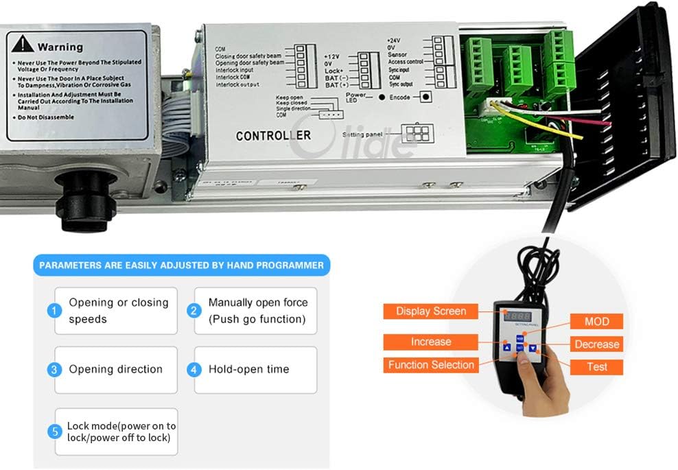
Image 5.3: Close-up of the door operator's internal controller board and the handheld programmer. The image highlights the connection point for the programmer and lists adjustable parameters such as opening/closing speeds, manual open force, opening direction, hold-open time, and lock mode.
6. Operating Instructions
6.1 Automatic Operation via Push Button
To open both doors simultaneously, press one of the handicap push buttons. The doors will open to their programmed angle and remain open for the set hold-open time before closing automatically.

Image 6.1: A person pressing a handicap push button to activate the automatic dual door system, demonstrating the ease of access provided by the system.

Image 6.2: A person in a wheelchair approaching an automatic dual door system, illustrating the system's benefit for accessibility.
6.2 Manual Operation
In manual mode, the doors can be opened with minimal pressure. This allows for manual passage if automatic operation is not desired or in case of power failure. The doors will close slowly after manual opening.
6.3 Programming Parameters
Use the handheld programmer to adjust various operational parameters. Connect the programmer to the door operator's controller as shown in Image 5.3.
- Opening or Closing Speeds: Adjust the speed at which the doors open and close.
- Manually Open Force (Push Go Function): Set the force required for manual opening.
- Opening Direction: Configure for inswing or outswing operation.
- Hold-Open Time: Set the duration the doors remain open after activation. This can also be set to keep the doors permanently open.
- Lock Mode: Configure power-on to lock or power-off to lock behavior.
Refer to the handheld programmer's specific manual for detailed instructions on navigating its menu and adjusting each parameter.
7. Maintenance
Regular maintenance ensures the longevity and reliable operation of your Olideauto Automatic Dual Door Operator.
- Monthly: Inspect all mounting hardware for tightness. Check for any signs of wear on moving parts.
- Quarterly: Clean the door operator housing and push buttons with a soft, damp cloth. Ensure sensors (if installed separately) are clear of obstructions.
- Annually: Have a qualified technician inspect the motor, gears, and electrical connections. Check battery health if applicable.
- Do not use abrasive cleaners or solvents on any part of the system.
8. Troubleshooting
This section addresses common issues you might encounter with your automatic door operator. For problems not listed here, or if solutions do not resolve the issue, please contact technical support.
| Problem | Possible Cause | Solution |
|---|---|---|
| Doors do not open when push button is pressed. | No power to the unit; loose wiring; faulty push button; receiver not paired. | Check power supply; inspect all wiring connections; test push button functionality; re-pair receiver with push button (refer to receiver manual). |
| Doors open partially or slowly. | Incorrect speed setting; obstruction; low voltage. | Adjust opening speed using handheld programmer; check for physical obstructions; verify power supply voltage. |
| Doors do not close completely. | Obstruction in closing path; incorrect closing force setting; faulty sensor. | Remove any obstructions; adjust closing force via handheld programmer; inspect and clean sensors. |
| Push buttons get stuck. | Mechanical issue with button housing. | Inspect the button for debris or misalignment. If necessary, carefully sand down edges to prevent sticking. |
| One door operates, the other does not. | Wiring issue to the non-operating unit; faulty operator unit. | Check power and signal wiring to the affected door operator. Consult technical support if wiring is correct. |
9. Warranty and Support
9.1 Product Warranty
The Olideauto Automatic Dual Door Operator comes with a 60-month product warranty from the date of purchase. This warranty covers defects in materials and workmanship under normal use. Please retain your proof of purchase for warranty claims.
9.2 Technical Support
For any installation, programming, or troubleshooting assistance, USA Technical phone support is available. Please refer to your product packaging or the Olideauto website for contact information.


