1. Introduction
The Walfront ESP32-IO Development Board is an expansion module designed to facilitate the use and debugging of ESP-WROOM-32 modules. Constructed from high-quality PCB material, this board provides convenient access to the ESP32's pins, making it suitable for students, engineers, technicians, and DIY enthusiasts involved in electronics development and programming. It integrates essential features such as a power control switch and standard headers to streamline your projects.
2. Product Overview
The ESP32-IO Development Board serves as a breakout board for the ESP-WROOM-32 module, expanding its GPIO pins to standard headers for easier prototyping.
2.1 Key Features
- High-Quality PCB Material: Ensures durability and reliable performance.
- Expanded Pin Access: Provides convenient access to ESP-WROOM-32 module pins for easy peripheral connection.
- Integrated Power Control: Features a dedicated power switch for easy power management.
- Standard Headers: Designed for straightforward development and debugging.
- Wide Application: Ideal for educational purposes, engineering projects, and DIY electronics.
2.2 Board Components
Refer to the diagram below for an identification of the main components on the Walfront ESP32-IO Development Board.

Figure 1: Walfront ESP32-IO Development Board with key components labeled. This image shows the ESP32 control board pins, 3.3V and GND pins, the external power interface (DC 7-12V), a 5V voltage regulator chip, and the power control switch.
3. Setup Instructions
Follow these steps to set up your Walfront ESP32-IO Development Board.
- Insert ESP-WROOM-32 Module: Carefully align your ESP-WROOM-32 module with the central headers on the development board. Ensure all pins are correctly seated without bending. Note: Verify compatibility of your ESP32 module's pin spacing with the board's headers before insertion. Refer to the Troubleshooting section for more details on potential compatibility issues.
- Power Connection:
- External Power: Connect a DC power supply (7-12V) to the external power interface (barrel jack) on the board.
- USB Power (via ESP32 module): If your ESP32 module has a USB port, you can power the entire setup by connecting a USB cable to the module. The development board will draw power from the module.
- Power On: Flip the power control switch to the "ON" position. An indicator LED (if present on your ESP32 module) should illuminate.
- Connect Peripherals: Use jumper wires to connect your desired sensors, actuators, or other components to the expanded GPIO pins on the development board. Ensure correct voltage levels (3.3V or 5V) and ground connections.
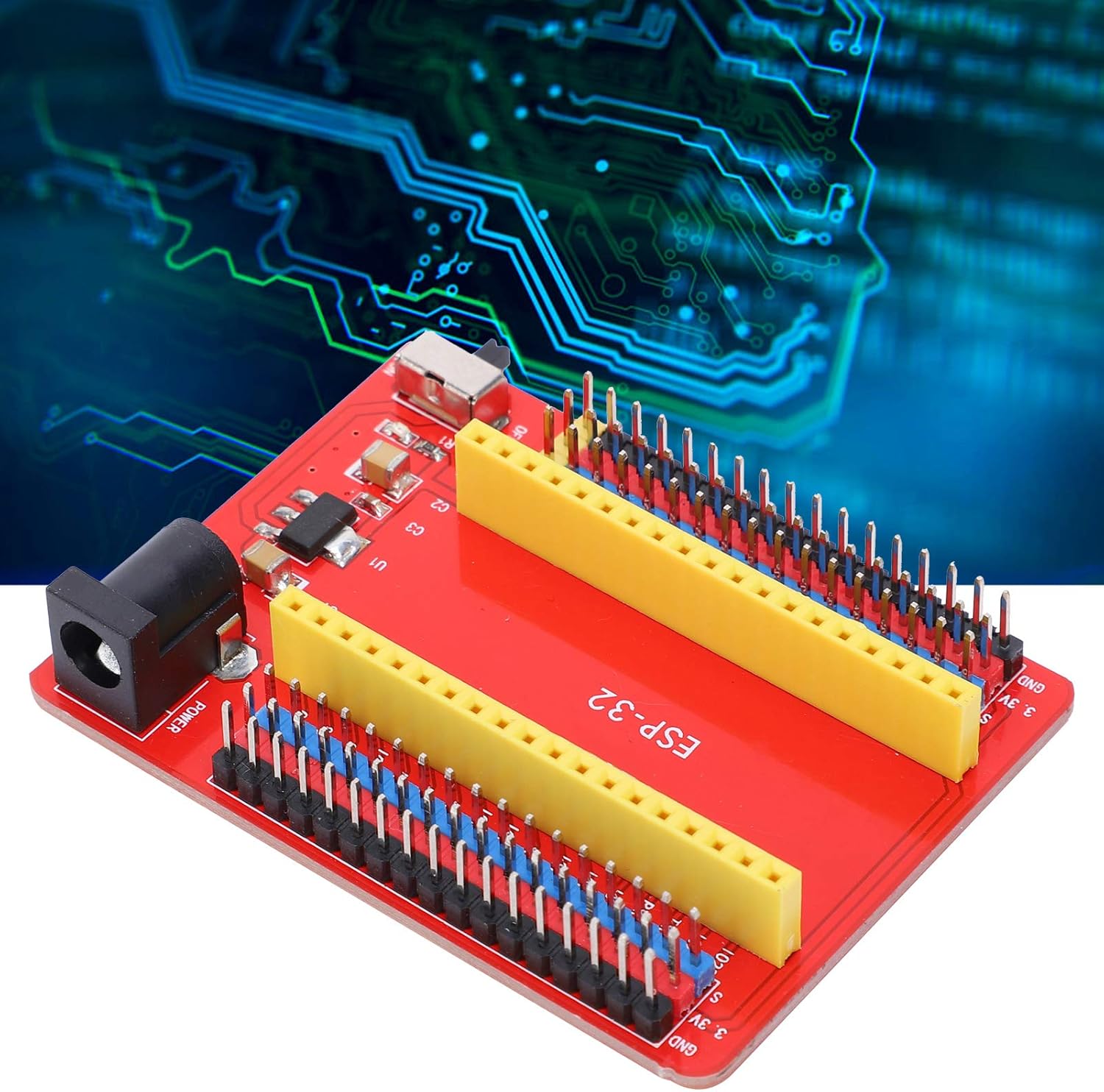
Figure 2: An angled view of the Walfront ESP32-IO Development Board, showing the pin headers and power input.
4. Operating Instructions
Once the ESP32-IO Development Board is set up with an ESP-WROOM-32 module, you can proceed with programming and testing your applications.
- Programming Environment: Use a suitable Integrated Development Environment (IDE) such as Arduino IDE or Espressif IDF. Ensure you have the correct board definitions and drivers installed for your ESP-WROOM-32 module.
- Code Upload: Connect your ESP32 module (if it has a USB port) to your computer. Select the correct COM port and board type in your IDE, then upload your code. The CP2102-GMR USB serial port chip on the development board facilitates communication.
- Utilizing Wi-Fi and Bluetooth: The ESP-WROOM-32 module supports Wi-Fi (802.11 b/g/n/e/i) and Bluetooth (v4.2 BR/EDR and BLE). Refer to the ESP32 documentation and examples for programming these wireless functionalities.
- Debugging: The expanded pins allow for easy connection of debugging tools or for monitoring GPIO states with a multimeter or oscilloscope.
5. Maintenance
Proper care and maintenance will extend the lifespan of your development board.
- Cleaning: Use a soft, dry cloth to clean the board. For stubborn dirt, a small amount of isopropyl alcohol on a cotton swab can be used, ensuring the board is powered off and completely dry before re-powering.
- Storage: Store the board in a dry, anti-static environment, away from direct sunlight and extreme temperatures.
- Handling: Always handle the board by its edges to avoid touching components and pins, which can cause damage or introduce static discharge.
- Power Off: Disconnect power before making any physical changes or connections to the board.
6. Troubleshooting
This section addresses common issues you might encounter with the Walfront ESP32-IO Development Board.
6.1 Board Not Powering On
- Check Power Switch: Ensure the power control switch is in the "ON" position.
- Verify Power Source: Confirm that the external DC power supply (7-12V) is correctly connected and providing power, or that the USB cable to the ESP32 module is functional.
- Module Seating: Ensure the ESP-WROOM-32 module is correctly and firmly seated in the headers.
6.2 Incompatible Pin Spacing for ESP32 Modules
Users have reported that the pin spacing on the Walfront ESP32-IO Development Board may be too narrow for some standard ESP32 NodeMCU modules, including those from popular manufacturers. This can prevent the ESP32 module from being properly inserted into the expansion board's headers.
- Verify Module Compatibility: Before purchase, compare the pin spacing of your specific ESP32 module with the dimensions of this development board (refer to the 'Specifications' section for board dimensions).
- Alternative Modules: If your ESP32 module does not fit, consider using an ESP32 module specifically designed to be compatible with this board's pin layout, or explore alternative development boards.
- Caution: Attempting to force an incompatible module into the headers may damage both the module and the development board. Bending pins to fit is not recommended as it can lead to unreliable connections or permanent damage.
6.3 Programming Errors
- Driver Installation: Ensure the correct drivers for the CP2102-GMR USB serial chip are installed on your computer.
- IDE Settings: Double-check that the correct board type and COM port are selected in your IDE.
- Module State: Some ESP32 modules require specific button presses (e.g., BOOT button) during code upload. Refer to your ESP32 module's documentation.
7. Specifications
Detailed technical specifications for the Walfront ESP32-IO Development Board.
| Feature | Specification |
|---|---|
| Product Type | Development Board |
| Material | High-Quality PCB |
| Compatible Microcontroller | ESP-WROOM-32 Module |
| USB Serial Port Chip | CP2102-GMR |
| Operating Current | 60 mA |
| Maximum Power | 0.3 W |
| Operating Temperature | -25 °C to 65 °C |
| Wi-Fi Mode | Station/SoftAP/SoftAP+Station/P2P |
| Wi-Fi Protocol | 802.11 b/g/n/e/i (802.11n up to 150 Mbps) |
| WLAN Frequency Range | 2.4 GHz - 2.5 GHz |
| Bluetooth Protocol | Bluetooth v4.2 BR/EDR and BLE standards |
| Connectivity Technology | Wi-Fi |
| Wireless Communication Standard | 802.11b |
| Processor Count | 1 (referring to the ESP32 module) |
7.1 Dimensions

Figure 3: Dimensions of the Walfront ESP32-IO Development Board. The board measures approximately 67mm in length and 50mm in width. The internal spacing for the ESP32 module is approximately 22.86mm.
8. Safety Information
Observe the following safety precautions to prevent injury or damage to the device.
- Do not expose the board to moisture or extreme temperatures.
- Ensure proper ventilation when operating to prevent overheating.
- Always use the specified power supply voltage (DC 7-12V for external power). Using incorrect voltage can damage the board.
- Avoid short circuits on the pins.
- Keep out of reach of children.
9. Warranty and Support
For warranty information or technical support, please contact your retailer or the manufacturer, Walfront, directly. Keep your purchase receipt for any warranty claims.


