
1. Introduction
This manual provides essential information for the safe and effective use of the Omron G7S-4A2B-E DC24 Power Relay. Please read this manual thoroughly before installation, operation, or maintenance to ensure proper handling and to prevent accidents.
2. Safety Information
WARNING: Electrical shock hazard. Always disconnect power before installing, servicing, or removing this device. Only qualified personnel should perform installation and maintenance.
- Ensure all wiring complies with local and national electrical codes.
- Do not exceed the specified voltage and current ratings.
- Verify correct terminal connections before applying power.
- Avoid touching live terminals.
- Install in an environment free from excessive moisture, dust, corrosive gases, or vibration.
3. Product Overview
The Omron G7S-4A2B-E DC24 is a power relay featuring forcibly guided contacts, designed for applications requiring high safety and reliability. It includes 6 poles with a configuration of 4 Normally Open (NO) and 2 Normally Closed (NC) contacts. The relay operates with a 24VDC coil and is rated for switching up to 10A at 250VAC or 30VDC.
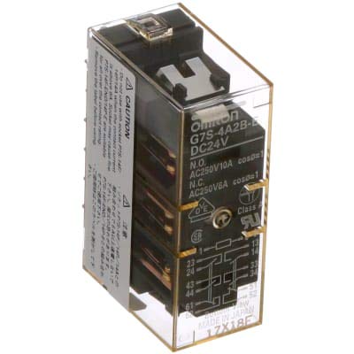
Image of the Omron G7S-4A2B-E DC24 Power Relay, showing its compact form factor and terminal layout.
4. Setup and Installation
Installation should be performed by a qualified electrician or technician.
4.1 Mounting
- Mount the relay securely in a suitable enclosure to protect it from environmental factors.
- Ensure adequate ventilation around the relay to prevent overheating.
4.2 Wiring
- Identify the coil terminals (typically marked A1, A2 or similar) and connect them to the 24VDC power supply. Observe polarity if indicated.
- Connect the load circuits to the contact terminals. This relay features 4 Normally Open (NO) and 2 Normally Closed (NC) contacts. Refer to the product's terminal diagram for specific pin assignments.
- Use appropriate wire gauges for the current rating to prevent overheating.
- Ensure all connections are tight and secure.
5. Operating Instructions
The G7S-4A2B-E DC24 relay operates automatically based on the energization of its coil.
- Energizing the Coil: When 24VDC is applied to the coil terminals, the relay will actuate. The Normally Open (NO) contacts will close, and the Normally Closed (NC) contacts will open.
- De-energizing the Coil: When the 24VDC supply to the coil is removed, the relay will de-actuate. The NO contacts will open, and the NC contacts will close, returning to their default states.
- The forcibly guided contacts ensure that all contacts move together, preventing situations where one contact might weld while others remain open, enhancing safety in critical applications.
6. Maintenance
Regular inspection and maintenance can extend the lifespan and ensure reliable operation of the relay.
- Visual Inspection: Periodically check for any signs of physical damage, discoloration due to overheating, or loose connections.
- Cleaning: Keep the relay free from dust and debris. Use a dry, soft cloth for cleaning. Do not use solvents.
- Contact Check: In critical applications, periodically verify the contact operation and resistance. Replace the relay if contacts show excessive wear or pitting.
- Power Cycle: Ensure power is disconnected before performing any maintenance.
7. Troubleshooting
If the relay is not functioning as expected, perform the following basic checks:
- Relay Not Actuating:
- Verify that the 24VDC coil voltage is present and stable at the coil terminals.
- Check for correct coil polarity if applicable.
- Inspect coil terminals for loose connections or damage.
- Contacts Not Switching:
- Ensure the coil is properly energized.
- Check the load circuit wiring for continuity and correct connections.
- Verify that the load current and voltage do not exceed the relay's contact ratings.
- Intermittent Operation:
- Check for loose wiring connections at both the coil and contact terminals.
- Ensure the power supply to the coil is stable and free from voltage fluctuations.
- Inspect the operating environment for excessive vibration or temperature changes.
If issues persist after these checks, contact Omron technical support or a qualified service professional.
8. Specifications
| Specification | Value |
|---|---|
| Brand | Omron |
| Model | G7S-4A2B-E DC24 |
| Contact Type | Forcibly Guided, 4NO/2NC (6 Pole) |
| Coil Voltage | 24 Volts DC |
| Maximum Switching Current | 10 Amps (for NO contacts) |
| Maximum Switching Voltage | 250 Volts AC / 30 Volts DC |
| Operation Mode | Automatic |
| Item Weight | 8.99 pounds |
| UPC | 040048838418 |
9. Warranty and Support
Omron products are manufactured to high-quality standards and are typically covered by a manufacturer's warranty against defects in materials and workmanship. For specific warranty terms, duration, and to obtain technical support or service, please refer to the official Omron website or contact your local Omron distributor.
Manufacturer: OMRON Corp


