CNLW W3230
W3230 Digital Temperature Control Thermostat User Manual
Brand: CNLW | Model: W3230
1. Introduction
The CNLW W3230 is a versatile digital temperature control instrument designed for precise temperature management in various applications. It features an LED display for clear readings and supports both heating and cooling control modes. This manual provides essential information for the proper installation, operation, and maintenance of your W3230 thermostat.

Figure 1: Front view of the W3230 Digital Temperature Controller, showing the LED display and control buttons.
2. Product Features
- Model: W3230
- Temperature Range: -50 to 120℃
- Resolution: 0.1 ℃ (-9.9 to 99.9 ℃); 1℃ (other temperature ranges)
- Measurement Accuracy: 0.1℃
- Control Accuracy: 0.1℃
- Return Difference Accuracy: 0.1℃
- Refresh Rate: 0.5 seconds
- Display Color: Red (PV) + Blue (SV)
3. Panel Overview
Familiarize yourself with the control panel components for effective operation.
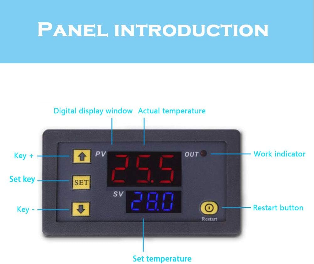
Figure 2: Labeled diagram of the W3230 control panel.
- PV (Process Value) Display (Red): Shows the current actual temperature measured by the probe.
- SV (Set Value) Display (Blue): Shows the desired set temperature.
- OUT Indicator: Illuminates when the relay output is active (heating or cooling).
- SET Key: Used to enter the setting mode and confirm selections.
- Up Arrow Key (+): Increases values or navigates menu options.
- Down Arrow Key (-): Decreases values or navigates menu options.
- Restart Button: Resets the device or clears certain settings.
4. Specifications
Detailed technical specifications of the W3230 thermostat.

Figure 3: Image illustrating various voltage specifications available for the W3230.
| Specification | Value |
|---|---|
| Manufacturer | CNLW |
| Part Number | LW002609 |
| Size | 110-220V (model variant) |
| Shape | Rectangular |
| Item Package Quantity | 1 |
| Color | Blue, Red (Display) |
| Voltage Options | 12 Volts, 24 Volts, 110-220 Volts (depending on model) |
| Display Type | LED |
| Operating Temperature | -50 to 120℃ |
5. Installation & Wiring
5.1. Dimensions
Ensure adequate space for mounting the thermostat. Refer to the dimensions below.

Figure 4: Dimensional drawing of the W3230 thermostat (in millimeters).
- Front Panel Size: 79mm (width) x 43mm (height)
- Mounting Hole Size: Typically 76mm x 39mm (check specific model for exact cutout)
- Depth: 26mm (main body) + 24mm (terminal block)
5.2. Wiring Diagram
WARNING: Ensure power is disconnected before performing any wiring. Incorrect wiring can cause damage to the device or pose a safety hazard. If you are unsure, consult a qualified electrician.

Figure 5: Wiring diagram for the 110-220V W3230 model.
- +VCC / -GND: Power input terminals. Connect your power supply (12V, 24V, or 110-220V depending on your model) to these terminals. Ensure correct polarity for DC models.
- S1 / S2: Temperature sensor input terminals. Connect the NTC temperature probe to these terminals. Polarity does not matter for the sensor.
- Load (Relay Output): These are the relay output terminals. Connect your heating or cooling device (load) to these terminals. The relay acts as a switch, opening or closing the circuit to control your load based on the temperature settings.
6. Operating Instructions
6.1. Power On
After correct wiring, apply power to the thermostat. The PV display will show the current temperature, and the SV display will show the set temperature.
6.2. Setting Temperature
- Press the SET button once. The SV display will start flashing.
- Use the Up Arrow (+) and Down Arrow (-) keys to adjust the desired temperature (SV).
- Press the SET button again to confirm the setting and exit the temperature setting mode. If no button is pressed for a few seconds, it will automatically save and exit.
6.3. Setting Operating Mode (Heating/Cooling) and Parameters
The W3230 typically has various programmable parameters (P0-P6) to configure its operation, such as heating/cooling mode, hysteresis, temperature correction, etc.
- Press and hold the SET button for approximately 3-5 seconds until the display shows "P0". This enters the parameter setting mode.
- Use the Up Arrow (+) or Down Arrow (-) keys to navigate through the parameters (P0, P1, P2, etc.).
- Once you are on the desired parameter (e.g., P0 for heating/cooling mode), press the SET button once. The value for that parameter will flash.
- Use the Up Arrow (+) or Down Arrow (-) keys to change the parameter's value.
- P0 (Heating/Cooling Mode): Set to 'H' for Heating (output turns on when temperature is below set point) or 'C' for Cooling (output turns on when temperature is above set point).
- P1 (Hysteresis/Return Difference): Sets the temperature difference before the relay switches back.
- Other parameters (P2-P6) may include maximum/minimum set limits, temperature correction, delay start, etc. Refer to specific model documentation for full details.
- Press the SET button again to confirm the parameter value.
- To exit the parameter setting mode, press and hold the SET button again for 3-5 seconds, or wait for it to automatically exit after a period of inactivity.
6.4. Restart Function
Press the Restart button to reset the device. This may clear temporary settings or restart the control cycle.
7. Maintenance
- Keep the device clean and free from dust. Use a soft, dry cloth for cleaning.
- Avoid exposing the thermostat to extreme temperatures, humidity, or corrosive environments.
- Regularly check wiring connections to ensure they are secure.
- Do not attempt to open the casing or repair the device yourself, as this may void the warranty and pose a safety risk.
8. Troubleshooting
| Problem | Possible Cause | Solution |
|---|---|---|
| Display shows "LLL" or "HHH" | Sensor open circuit (LLL) or short circuit/temperature exceeding range (HHH). | Check sensor connection. Replace sensor if damaged. Ensure temperature is within -50 to 120℃ range. |
| No display/No power | No power supply or incorrect wiring. | Verify power connections and voltage. Check wiring against diagram. |
| Output (OUT indicator) not activating | Incorrect temperature setting, wrong mode (heating/cooling), or faulty relay. | Adjust set temperature. Check P0 parameter for correct mode. Ensure load is connected properly. |
| Temperature reading inaccurate | Sensor placement, temperature correction setting (P4). | Relocate sensor to a representative area. Adjust P4 for calibration if needed. |
9. Warranty & Support
This product is covered by a standard manufacturer's warranty against defects in materials and workmanship. For specific warranty terms and conditions, please refer to the documentation provided with your purchase or contact your retailer.
For technical support or inquiries, please contact the manufacturer or your point of purchase. When contacting support, please provide your product model (W3230) and a detailed description of the issue.
Related Documents - W3230
 |
W3230 Digital Temperature Controller with K-Type Thermocouple Comprehensive guide to the W3230 digital temperature controller, featuring a K-type thermocouple. Details include specifications, features like ultra-wide temperature range (-60°C to 500°C), smart control modes, power-off memory, and operational instructions for setting temperature and parameters. Suitable for various applications including refrigeration, industrial control, and agriculture. |
 |
W3230 Digital Temperature Controller Module User Guide User guide for the W3230 digital temperature controller module, detailing its features, installation, wiring, and temperature settings for precise temperature control in various applications. |
 |
W3230/W3231 AC/DC Digital Thermostat Temperature Control Module User Manual Detailed user manual for the W3230 and W3231 AC/DC Digital Thermostat Temperature Control Modules, covering operation, parameter settings, wiring, and troubleshooting. Includes specifications and operational guidance. |
 |
W3230 Digital Temperature Controller: K-Type Thermostat for Heating & Cooling Comprehensive details on the W3230 digital temperature controller, featuring K-type thermocouple input, dual LED displays, wide voltage compatibility (12V/24V DC, 110-220V AC), and precise heating/cooling control for industrial, agricultural, and other applications. |
 |
Microcomputer Temperature Controller User Manual and Specifications Detailed specifications, function descriptions, operating instructions, and wiring diagrams for the Microcomputer Temperature Controller. Covers temperature control ranges, accuracy, power supply options, and parameter settings for refrigeration and heating modes. |