1. Introduction
This manual provides detailed instructions for the installation, operation, and maintenance of your GIGABYTE Z590 AORUS Master motherboard. Designed for 11th and 10th Generation Intel Core Series Processors, this motherboard offers advanced features and robust performance for high-end computing systems. Please read this manual thoroughly before proceeding with installation to ensure proper setup and functionality.

Image 1.1: GIGABYTE Z590 AORUS Master Motherboard and Retail Box. This image shows the motherboard alongside its packaging, providing a visual reference for the product as received.
2. Key Features
The GIGABYTE Z590 AORUS Master motherboard incorporates several advanced technologies and design elements:
- Supports 11th and 10th Generation Intel Core Series Processors.
- Dual Channel Non-ECC Unbuffered DDR4 memory, with 4 DIMM slots.
- 18+1 Phases Digital VRM Solution with 90A Smart Power Stage and Tantalum Polymer Capacitors Array for stable power delivery.
- Advanced Thermal Solution featuring Fins-Array II, Direct Touch Heatpipe II, and NanoCarbon Baseplate for efficient heat dissipation.
- Onboard Intel Wi-Fi 6E 802.11ax 2T2R & BT 5 with AORUS Antenna for high-speed wireless connectivity.
- AQUANTIA 10GbE BASE-T LAN with cFosSpeed for ultra-fast wired networking.
- Triple Ultra-Fast NVMe PCIe 4.0*/3.0 x4 M.2 slots with Thermal Guards II for high-performance storage.
- RGB FUSION 2.0 with Multi-Zone Addressable LED Light Show Design.
- Q-Flash Plus for BIOS updates without CPU, memory, or graphics card installation.
3. Motherboard Layout
Familiarize yourself with the various components and connectors on the motherboard.

Image 3.1: GIGABYTE Z590 AORUS Master Motherboard Overview. This image displays the full top-down view of the motherboard, highlighting the CPU socket, DIMM slots, PCIe slots, and M.2 heatsinks.
3.1. CPU Socket (LGA 1200)
The central LGA 1200 socket is designed for Intel 10th and 11th Generation Core processors. Ensure correct CPU orientation before installation.
3.2. Memory Slots (DIMM)
Four DDR4 DIMM slots support dual-channel memory configurations. Refer to the motherboard's qualified vendor list (QVL) for compatible memory modules.
3.3. Expansion Slots (PCIe)
Multiple PCIe slots are available for graphics cards and other expansion cards. The primary PCIe x16 slot is reinforced for heavy graphics cards.
3.4. M.2 Connectors
Three M.2 slots are provided for NVMe SSDs, each covered by a Thermal Guard II heatsink for optimal performance.
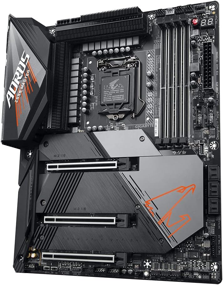
Image 3.2: M.2 Slots with Thermal Guards. This angled view emphasizes the three M.2 slots, each equipped with a heatsink to manage SSD temperatures.
3.5. Rear I/O Panel
The rear panel provides various ports for external devices.
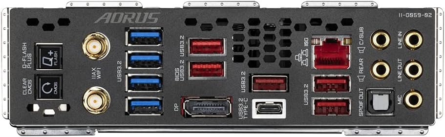
Image 3.3: Rear I/O Panel. This image shows the array of ports on the back of the motherboard, including USB, Ethernet, audio jacks, and Wi-Fi antenna connectors.
- USB Ports: Multiple USB 3.2 Gen 2x2 Type-C, USB 3.2 Gen 2 Type-A, and USB 3.2 Gen 1 Type-A ports.
- Network: AQUANTIA 10GbE LAN port.
- Audio: Optical S/PDIF Out, Line In, Line Out, Mic In, Rear Speaker Out, Center/Subwoofer Speaker Out.
- Display: DisplayPort.
- Wireless: Wi-Fi 6E antenna connectors.
- Buttons: Q-Flash Plus button, Clear CMOS button.
4. Installation Guide
Follow these steps carefully to install your motherboard and its components.
4.1. CPU Installation
- Open the CPU socket lever.
- Carefully align the CPU with the socket, ensuring the triangular mark on the CPU matches the mark on the socket.
- Gently place the CPU into the socket without forcing it.
- Close the CPU socket lever to secure the CPU.
4.2. Memory (RAM) Installation
- Open the clips at both ends of the DIMM slot.
- Align the notch on the DDR4 memory module with the key in the DIMM slot.
- Insert the memory module firmly until the clips snap into place.
- For dual-channel operation, install modules in matching color slots (e.g., DDR4_A2 and DDR4_B2 first).
4.3. Storage Device Installation
4.3.1. M.2 SSD Installation
- Unscrew and remove the M.2 Thermal Guard II heatsink from the desired M.2 slot.
- Insert the M.2 SSD into the slot at a 30-degree angle.
- Gently push down the SSD and secure it with the provided M.2 screw.
- Reattach the Thermal Guard II heatsink and secure it with screws.
4.3.2. SATA Drive Installation
Connect SATA data cables from your SATA drives (HDDs/SSDs) to the SATA ports on the motherboard. Connect SATA power cables from your power supply to the drives.
4.4. Expansion Card Installation (e.g., Graphics Card)
- Align your PCIe expansion card with the desired PCIe slot.
- Press down firmly until the card is seated correctly and the retention clip engages.
- Secure the card to the chassis with a screw.
4.5. Connecting Peripherals
Connect front panel headers (power button, reset button, USB, audio) using the G-Connector for easier installation. Connect USB devices, audio devices, and network cables to the rear I/O panel.
4.6. Power Supply Connection
Connect the 24-pin ATX main power connector and the 8-pin + 4-pin CPU power connectors from your power supply to the corresponding ports on the motherboard.
5. Initial Setup and BIOS
5.1. First Boot
After assembling all components, connect your monitor, keyboard, and mouse. Power on your system. The system should display the GIGABYTE splash screen.
5.2. Accessing BIOS/UEFI
During startup, repeatedly press the DEL key to enter the BIOS Setup Utility. Here you can configure system settings, boot order, and enable features like XMP for memory overclocking.
5.3. Q-Flash Plus
The Q-Flash Plus feature allows you to update the BIOS without installing the CPU, memory, or graphics card. Simply download the latest BIOS file from the GIGABYTE website, rename it to GIGABYTE.bin, save it to a USB flash drive, and insert it into the designated Q-Flash Plus USB port on the rear I/O panel. Press the Q-Flash Plus button to initiate the update.
6. Driver and Software Installation
6.1. Operating System Installation
Install your preferred operating system (e.g., Windows 10/11) from a bootable USB drive or optical disc.
6.2. Driver Installation
After OS installation, install the necessary drivers for the chipset, LAN, audio, Wi-Fi, and other components. These can be found on the GIGABYTE support website for your specific motherboard model.
6.3. Utility Software
GIGABYTE provides various utility software to enhance your experience, including:
- RGB FUSION 2.0: For customizing RGB lighting effects.
- Smart Fan 6: For advanced fan control and monitoring.
- APP Center: A central hub for GIGABYTE utilities and drivers.
7. Maintenance and Care
7.1. Cleaning
Regularly clean your system to prevent dust buildup, which can lead to overheating. Use compressed air to remove dust from heatsinks, fans, and other components. Ensure the system is powered off and unplugged before cleaning.
7.2. BIOS and Driver Updates
Keep your BIOS and drivers updated to ensure optimal performance, stability, and compatibility with new hardware or software. Check the GIGABYTE website periodically for the latest versions.
8. Troubleshooting
If you encounter issues, refer to the following common troubleshooting steps.
8.1. No Power / No Boot
- Verify all power cables (24-pin ATX, 8-pin CPU, 4-pin CPU) are securely connected.
- Ensure the power supply is switched on.
- Check front panel power switch connection.
8.2. No Display
- Ensure the monitor is connected to the graphics card (if dedicated) or the motherboard (if using integrated graphics).
- Reseat the graphics card and memory modules.
- Try booting with a single RAM stick.
8.3. Clear CMOS
If the system becomes unstable or fails to boot after BIOS changes, clear the CMOS settings. This can be done by:
- Powering off the system and unplugging the power cord.
- Pressing the Clear CMOS button on the rear I/O panel.
- Alternatively, removing the CMOS battery for 1-5 minutes and then reinstalling it.
9. Product Specifications
| Feature | Specification |
|---|---|
| Brand | GIGABYTE |
| Model Name | Z590 AORUS MASTER |
| CPU Socket | LGA 1200 |
| Compatible Processors | 11th Generation Intel Core, 10th Generation Intel Core |
| Chipset Type | Intel Z590 |
| RAM Memory Technology | DDR4 |
| Memory Speed | 3200 MHz (up to 5400MHz+ OC) |
| RAM Slots | 4 x DDR4 DIMM, Dual Channel, Non-ECC Unbuffered |
| Wireless Type | 802.11ax (Wi-Fi 6E), Bluetooth 5 |
| LAN | AQUANTIA 10GbE BASE-T LAN |
| M.2 Slots | 3 x NVMe PCIe 4.0*/3.0 x4 M.2 with Thermal Guards II |
| USB 2.0 Ports | 2 (internal headers) |
| Product Dimensions | 12.01 x 9.61 x 1.57 inches (ATX Form Factor) |
| Item Weight | 4.11 pounds |
| Platform | Windows |
*Actual PCIe 4.0 support may vary by CPU.
10. Warranty and Support Information
For warranty details, technical support, and further assistance, please visit the official GIGABYTE website or contact their customer service. Keep your proof of purchase for warranty claims.
GIGABYTE Official Website: www.gigabyte.com


