
1. Introduction
This manual provides detailed instructions for assembling, operating, and maintaining your VOGURTIME FMT-VT10 FM Radio Transmitter Solder Project Kit. This kit is designed for electronics enthusiasts and beginners to enhance soldering skills and learn about FM radio transmission. Upon successful assembly, the kit functions as an FM radio transmitter, allowing you to broadcast audio to any standard FM radio receiver.

Figure 1: Fully assembled VOGURTIME FMT-VT10 FM Radio Transmitter.
2. Kit Contents
Before beginning assembly, please verify that all components listed below are present in your package. If any items are missing or damaged, please contact vogurtime-support@foxmail.com for assistance.
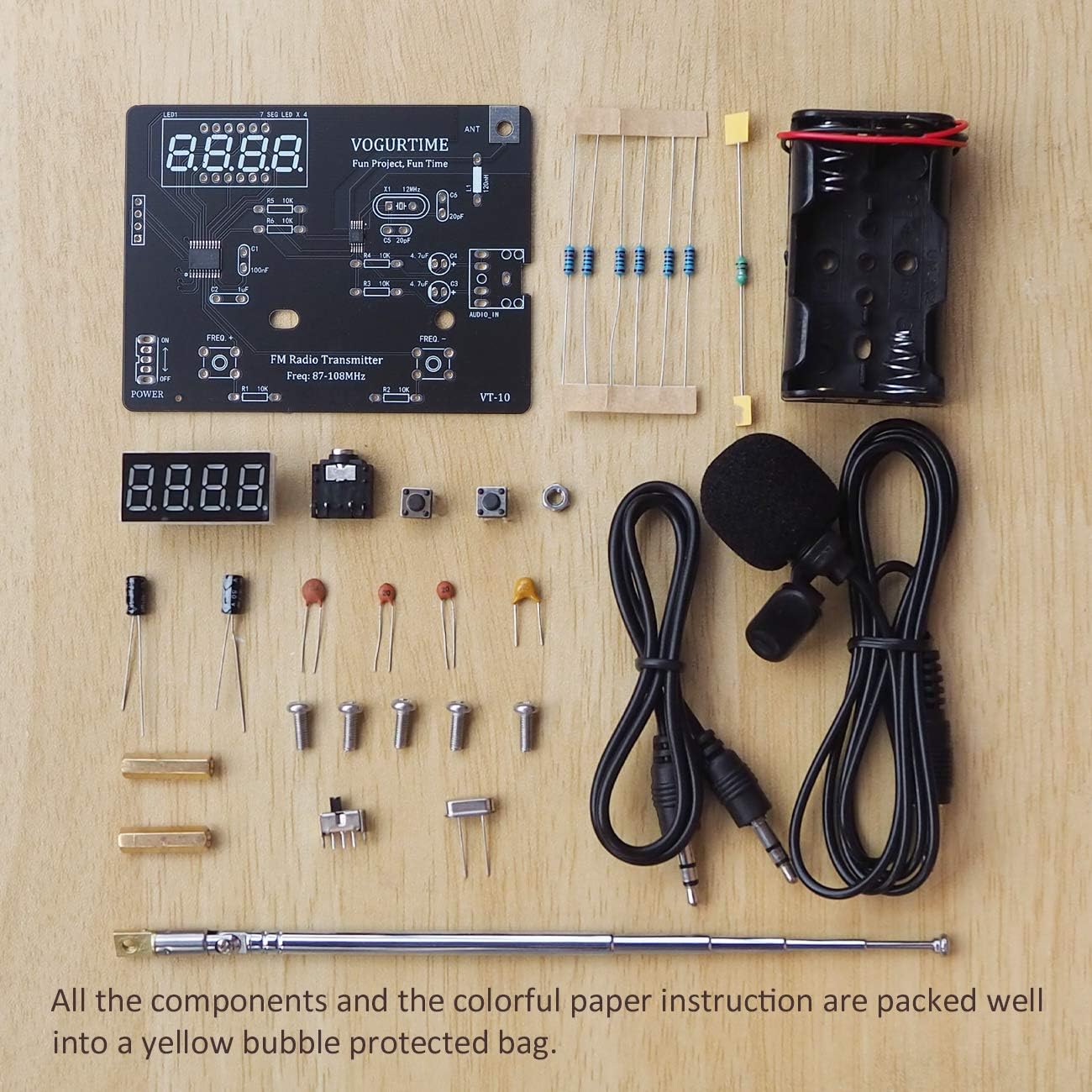
Figure 2: All components included in the kit.
- Printed Circuit Board (PCB)
- Resistors (various values)
- Capacitors (ceramic and electrolytic)
- Integrated Circuits (ICs) - Note: Two IC chips are pre-soldered on the board.
- Digital Display (7-segment LED)
- Tactile Switches (buttons for frequency adjustment)
- Crystal Oscillator
- Battery Holder (for 2 AA batteries, batteries not included)
- Retractable Antenna (approx. 31.5 cm / 12.4 inches)
- Lavalier Microphone (approx. 100 cm / 39.37 inches)
- 3.5mm Audio Cable (approx. 50 cm / 19.68 inches)
- Mounting hardware (screws, nuts)
- Instruction Manual (paper version)

Figure 3: Kit packaging showing components and instruction manual.
3. Setup and Assembly Instructions
This section guides you through the assembly process. Basic soldering skills are recommended. The two main IC chips are pre-soldered to simplify the process.
3.1 Basic Tools Required
- Soldering iron with a knife tip (recommended 40-60 watts, around 350°C/662°F with 1-2 seconds soldering time)
- Solder wire
- Diagonal knife/wire cutters
- Screwdriver
- Pair of nose pliers
- Rosin core (optional)
3.2 Soldering Tips
- Ensure all solder joints are fully filled onto the pads.
- Each solder joint should resemble a small hill; avoid solder skips, pseudo solder, or short-bridges.
- If you are new to electronics, practice soldering on scrap boards first.
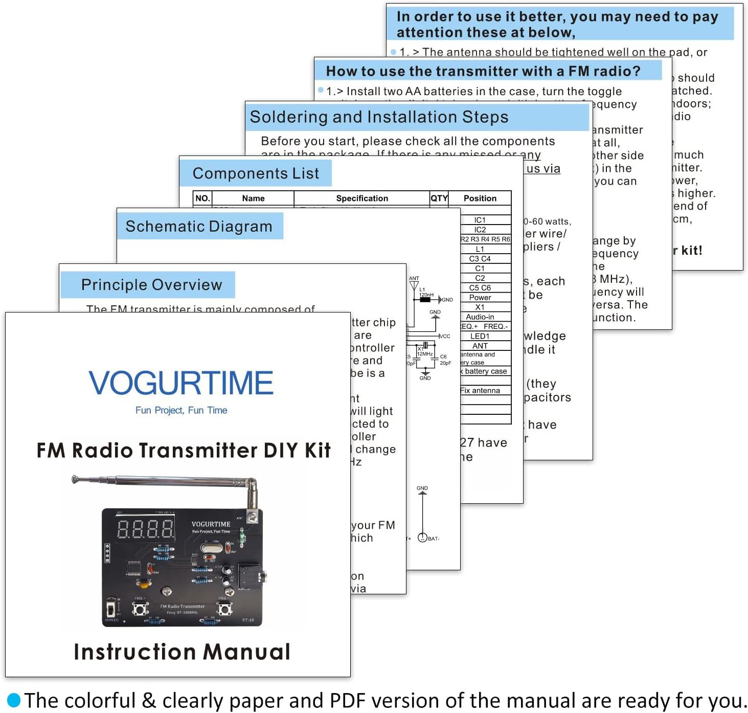
Figure 4: Excerpt from the instruction manual detailing soldering steps and tools.
3.3 Step-by-Step Assembly
- Solder Resistors and Capacitors: Solder the resistors (R1, R2, R3, R4, R5, R6), inductance L1, ceramic capacitors (C1, C5, C6), monolithic capacitors C2, crystal oscillator X1, and tact switches. These components do not have polarity, so orientation is not critical.
- Solder Digital Display: Carefully solder the 7-segment LED digital display to its designated pads.
- Install Battery Holder: Attach the battery holder to the PCB, ensuring correct polarity if applicable (usually marked + and -).
- Attach Antenna: Securely fasten the retractable antenna to the designated ANT pad on the board.
- Connect Wires: Solder any remaining wires according to the schematic diagram provided in the paper manual.

Figure 5: Front and back views of the assembled transmitter board.
3.4 Assembly Video Guide
For a visual guide on assembling a similar FM radio soldering kit, please refer to the video below. This video demonstrates general soldering practices and component placement that can be applied to your FMT-VT10 kit.
Video 1: Assembly process for an FM radio soldering kit. This video provides a general overview of soldering components onto a PCB, which is applicable to the FMT-VT10 kit.
4. Operating Instructions
Once assembled, follow these steps to operate your FM Radio Transmitter.
4.1 Powering On and Frequency Adjustment
- Insert Batteries: Install 2 AA batteries into the battery holder. Ensure correct polarity.
- Power On: Locate the ON/OFF switch (labeled 'POWER') and slide it to the 'ON' position. The digital display should illuminate.
- Adjust Frequency: Use the 'FREQ+' and 'FREQ-' buttons to set the desired transmission frequency. The operating frequency range is 87-108MHz. Try to select a frequency that is not occupied by a strong local radio station for optimal performance.

Figure 6: Labeled components for operation, including frequency display and adjustment buttons.
4.2 Connecting Audio Input
- Connect Microphone: Plug the lavalier microphone into the 3.5mm audio input jack. You can clip the microphone to your collar for hands-free broadcasting.
- Connect Audio Cable: Alternatively, connect an external audio source (e.g., smartphone, MP3 player) using the provided 3.5mm audio cable.
4.3 Receiving the Transmission
- Tune FM Radio: On your FM radio receiver, tune to the exact frequency displayed on your FMT-VT10 transmitter.
- Optimal Environment: For best results, operate the transmitter in an open area to minimize interference from indoor electromagnetic waves.
- Broadcast: Speak into the microphone or play audio from your connected device. The sound should now be audible through your FM radio receiver.
5. Maintenance
Proper maintenance ensures the longevity and optimal performance of your FMT-VT10 kit.
- Battery Replacement: Replace AA batteries when the digital display dims or transmission quality degrades. Always use fresh batteries and ensure correct polarity.
- Cleaning: Use a soft, dry cloth to clean the circuit board and external components. Avoid using liquids or abrasive cleaners.
- Storage: When not in use, store the kit in a dry, cool place away from direct sunlight and extreme temperatures. Remove batteries if storing for extended periods to prevent leakage.
6. Troubleshooting
If you encounter issues with your FMT-VT10 kit, refer to the following common problems and solutions:
- No Power/Display Not On:
- Check if batteries are inserted correctly with the right polarity.
- Ensure batteries are fresh and fully charged.
- Verify the power switch is in the 'ON' position.
- No Sound or Low Sound from Microphone/Audio Input:
- Ensure the microphone or audio cable is fully inserted into the 3.5mm jack. Some users have reported that pulling the plug out slightly from the jack can improve connection if the tolerances are not exact.
- Test with a different microphone or audio source if possible, as the included microphone may have varying performance.
- Verify that the FM radio receiver is tuned to the exact frequency displayed on the transmitter.
- Poor Transmission Quality/Interference:
- Extend the antenna fully on both the transmitter and receiver.
- Try adjusting the frequency to an unoccupied channel, especially avoiding frequencies used by strong local radio stations.
- Move the transmitter and receiver to an open area, away from potential sources of electromagnetic interference (e.g., computers, Wi-Fi routers, large metal objects).
- Ensure all soldered connections are solid and free from cold joints or short circuits.
- Incorrect Frequency Display:
- If the display shows incorrect values or is erratic, recheck the soldering of the digital display and its associated components.
7. Specifications
| Feature | Specification |
|---|---|
| Model Number | FMT-VT10 |
| Operating Frequency | 87-108 MHz |
| Power Source | 2 x AA Batteries (not included) |
| Microphone Length | 100 cm (39.37 inches) |
| Audio Cable Length | 50 cm (19.68 inches) |
| Antenna Length | 31.5 cm (12.4 inches), 5-section retractable |
| Finished Size (approx.) | 8.3 x 6.3 x 3.3 cm (3.3 x 2.5 x 1.3 inches) |
| Item Weight | 3.2 ounces |
| Manufacturer | VOGURTIME |
8. Warranty and Support
VOGURTIME is committed to providing quality products and customer satisfaction. If you have any questions, concerns, or require assistance with your FMT-VT10 kit, please do not hesitate to contact our support team.
Contact Email: vogurtime-support@foxmail.com
Please include your model number (FMT-VT10) and a detailed description of your inquiry for prompt assistance.