1. Product Overview
The MPRO-200 Motor Protection Relay is an industrial-grade device designed to protect motors from various electrical faults. This C&S Electric manufactured relay operates within a voltage range of 110-400V AC and a frequency of 50Hz. It is suitable for DIN rail mounting and features a robust design for reliable performance in industrial environments.
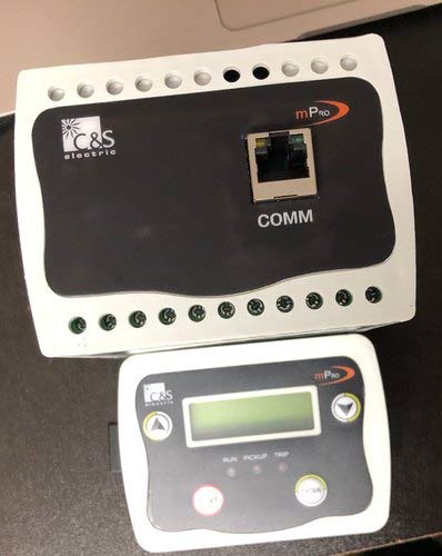
Figure 1: MPRO-200 Motor Protection Relay (main unit and display unit).
This image shows the main MPRO-200 relay unit, which is black with a white border and features a communication port (COMM) and screw terminals. Below it is the smaller, white display unit with a digital screen and control buttons.
Key Features:
- Voltage Range: 110-400V AC
- Application: Motor Protection
- Frequency: 50Hz
- Mounting Type: DIN Rail Mount
- Contact Type: Normally Open
- Contact Material: Silver
- Connector Type: Screw Terminals
- Operation Mode: Automatic
2. Safety Information
Always adhere to the following safety guidelines to prevent injury or damage to the equipment:
- Qualified Personnel Only: Installation, maintenance, and troubleshooting should only be performed by qualified electricians or technicians.
- Disconnect Power: Ensure all power sources are disconnected and locked out before performing any installation, wiring, or maintenance.
- Proper Grounding: Always ensure the device and associated equipment are properly grounded.
- Environmental Conditions: Do not expose the device to moisture, extreme temperatures, or corrosive environments.
- Wiring: Use appropriate wire gauges and follow all local and national electrical codes.
- Inspection: Regularly inspect the device for any signs of damage or wear.
3. Setup and Installation
The MPRO-200 is designed for easy installation on a standard DIN rail. Follow these steps for proper setup:
- Mounting: Securely mount the MPRO-200 main unit onto a DIN rail within an electrical enclosure.
- Wiring: Connect the motor's power lines through the designated current transformer (CT) inputs on the relay. Refer to the wiring diagram provided with the product packaging for specific terminal connections (e.g., A1, A2, B1, B2, etc.).
- Control Circuit Wiring: Connect the control circuit (e.g., contactor coil) to the relay's output contacts (Normally Open - NO, Normally Closed - NC, Common - C) as per your application's requirements.
- Power Supply: Connect the auxiliary power supply (110-400V AC) to the appropriate terminals on the relay.
- Display Unit Connection: Connect the separate display unit to the main relay unit using the provided communication cable. The display unit connects to the "COMM" port on the main relay.
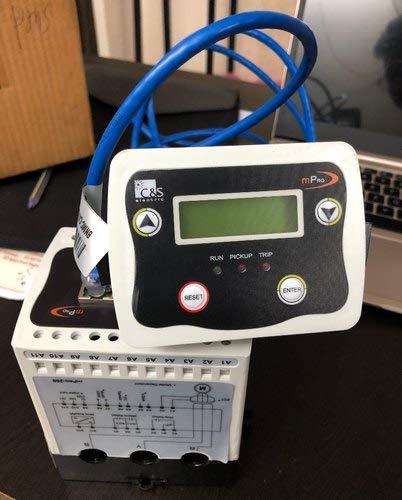
Figure 2: MPRO-200 Motor Protection Relay with display unit connected.
This image shows the MPRO-200 main relay unit from the side, revealing wiring diagrams and terminals. The display unit is shown connected to the main unit via a blue communication cable, highlighting the connectivity.
After all connections are made, double-check all wiring for correctness and security before applying power.
4. Operating Instructions
Once installed and powered, the MPRO-200 operates automatically to monitor motor parameters. The display unit provides real-time status and allows for configuration.
Display Unit Indicators and Controls:
- Digital Screen: Displays current motor parameters, fault codes, and menu options.
- RUN LED: Illuminates when the motor is operating normally.
- PICKUP LED: Illuminates when a fault condition is detected and the relay is in a "pickup" state, indicating an impending trip.
- TRIP LED: Illuminates when the relay has tripped due to a fault, disconnecting the motor.
- Arrow Buttons (Up/Down/Left/Right): Used for navigating through menu options and adjusting settings.
- ENTER Button: Confirms selections or enters sub-menus.
- RESET Button: Resets the relay after a trip condition has been cleared.
Basic Operation:
- Power On: Upon applying power, the display unit will initialize and show the default operating screen.
- Monitoring: The relay continuously monitors motor current, voltage, and other parameters. The RUN LED should be lit during normal operation.
- Fault Indication: If a fault occurs, the PICKUP and/or TRIP LEDs will illuminate, and a corresponding fault code or message may appear on the display.
- Resetting a Trip: After a trip, identify and clear the cause of the fault. Then, press the RESET button on the display unit to clear the trip and allow the motor to be restarted.
- Parameter Configuration: Use the arrow buttons and ENTER button to navigate the menu and configure protection parameters such as overload settings, under/over voltage limits, and trip delays. Refer to the detailed programming guide for specific menu structures and parameter definitions.
5. Maintenance
The MPRO-200 Motor Protection Relay is designed for minimal maintenance. However, periodic checks are recommended to ensure optimal performance and longevity:
- Visual Inspection: Annually inspect the relay for any signs of physical damage, loose connections, or discoloration due to overheating.
- Terminal Tightness: Check and re-tighten all screw terminals to ensure good electrical contact.
- Dust and Debris: Keep the relay and its enclosure free from dust and debris, which can affect cooling and performance. Use a soft, dry cloth or compressed air for cleaning.
- Functional Test: Periodically perform a functional test of the relay's trip mechanism, if possible, following established safety procedures.
6. Troubleshooting
If you encounter issues with your MPRO-200 relay, refer to the following common troubleshooting steps:
| Problem | Possible Cause | Solution |
|---|---|---|
| Relay does not power on. | No auxiliary power supply; Incorrect wiring; Blown fuse in control circuit. | Check power supply voltage; Verify wiring connections; Replace fuse if necessary. |
| Relay trips frequently. | Motor overload; Incorrect protection settings; Motor fault (e.g., bearing issue, short circuit). | Check motor load; Adjust protection settings (e.g., overload current, trip delay); Inspect motor for faults. |
| Display unit is blank or shows error. | Loose communication cable; Faulty display unit; Main unit power issue. | Ensure communication cable is securely connected; Check power to main unit; Contact support if display unit is faulty. |
| Cannot reset the relay. | Fault condition still present; Reset button malfunction. | Ensure the cause of the trip is cleared; Check reset button functionality. |
If the problem persists after attempting these solutions, contact qualified technical support.
7. Specifications
| Parameter | Value |
|---|---|
| Model | MPRO-200 |
| Brand | Generic (C&S Electric) |
| Usage/Application | Motor Protection |
| Voltage | 110-400V AC |
| Frequency | 50Hz |
| Mounting Type | DIN Rail Mount |
| Connector Type | Screw |
| Contact Material | Silver |
| Contact Type | Normally Open |
| Operation Mode | Automatic |
| Contact Current Rating | 10 Amps |
| Product Dimensions (LxWxH) | 20.35 x 15.25 x 20.35 cm |
| Item Weight | 500 g |
| Manufacturer | C&S Eletctric |
| Date First Available | 9 February 2021 |
8. Warranty and Support
Warranty Information:
This MPRO-200 Motor Protection Relay comes with a 1 Year Warranty from the date of purchase. The warranty covers manufacturing defects and malfunctions under normal operating conditions. It does not cover damage caused by improper installation, misuse, accidents, unauthorized modifications, or natural disasters.
Technical Support:
For technical assistance, troubleshooting, or warranty claims, please contact the manufacturer or your authorized distributor. Ensure you have your product model number (MPRO-200) and purchase details ready when contacting support.
Manufacturer: C&S Electric
For further assistance, please visit the official C&S Electric website or contact their customer service department.