1. Introduction
This manual provides detailed instructions for the safe and effective use of the LiebeWH DT9205B AC/DC Digital Multimeter. The DT9205B is a versatile tool designed for measuring AC/DC voltage, AC/DC current, resistance, capacitance, frequency, temperature, diode, and continuity. Its stable performance, clear LCD display, and overload protection make it suitable for various electrical testing applications, including computer repair, mobile phone inspection, and general circuit board diagnostics.
2. Safety Information
WARNING: To avoid electric shock or personal injury, please read and understand all safety information before using this multimeter.
- Always ensure the multimeter is in good working condition and the test leads are not damaged.
- Do not apply more than the rated voltage, as marked on the multimeter, between the terminals or between any terminal and ground.
- Use caution when working with voltages above 30V AC RMS, 42V peak, or 60V DC. These voltages pose a shock hazard.
- Always disconnect power to the circuit and discharge all high-voltage capacitors before measuring resistance, continuity, diodes, or capacitance.
- Ensure the rotary switch is set to the correct function and range before making measurements.
- Never measure current on a circuit with power applied unless the multimeter is connected in series with the load.
- Replace the battery immediately when the low battery indicator appears to ensure accurate readings.
- Do not operate the multimeter in explosive gas, vapor, or dusty environments.
3. Product Overview
The LiebeWH DT9205B Digital Multimeter features a clear LCD display and a robust rotary switch for selecting various measurement functions. It is designed for ease of use and durability.

Figure 3.1: Front view of the DT9205B Digital Multimeter with included test leads.

Figure 3.2: Close-up of the multimeter's LCD display, rotary function switch, and input jacks.
Key Components:
- LCD Display: Shows measurement readings, units, and indicators.
- Rotary Switch: Used to select the desired measurement function and range.
- Input Jacks: Terminals for connecting test leads (COM, VΩHz, mA, 20A).
- Test Leads: Red and black leads for connecting to the circuit under test.
- Power Button: To turn the device on/off.
4. Setup
4.1 Battery Installation
- Ensure the multimeter is turned off.
- Locate the battery compartment cover on the back of the unit.
- Use a screwdriver to remove the screw securing the cover.
- Insert a new 6F22-9V battery, observing the correct polarity (+/-).
- Replace the battery compartment cover and secure it with the screw.
4.2 Connecting Test Leads
- Insert the black test lead into the 'COM' (common) jack.
- For most voltage, resistance, and continuity measurements, insert the red test lead into the 'VΩHz' jack.
- For current measurements (mA), insert the red test lead into the 'mA' jack.
- For high current measurements (up to 20A), insert the red test lead into the '20A' jack.
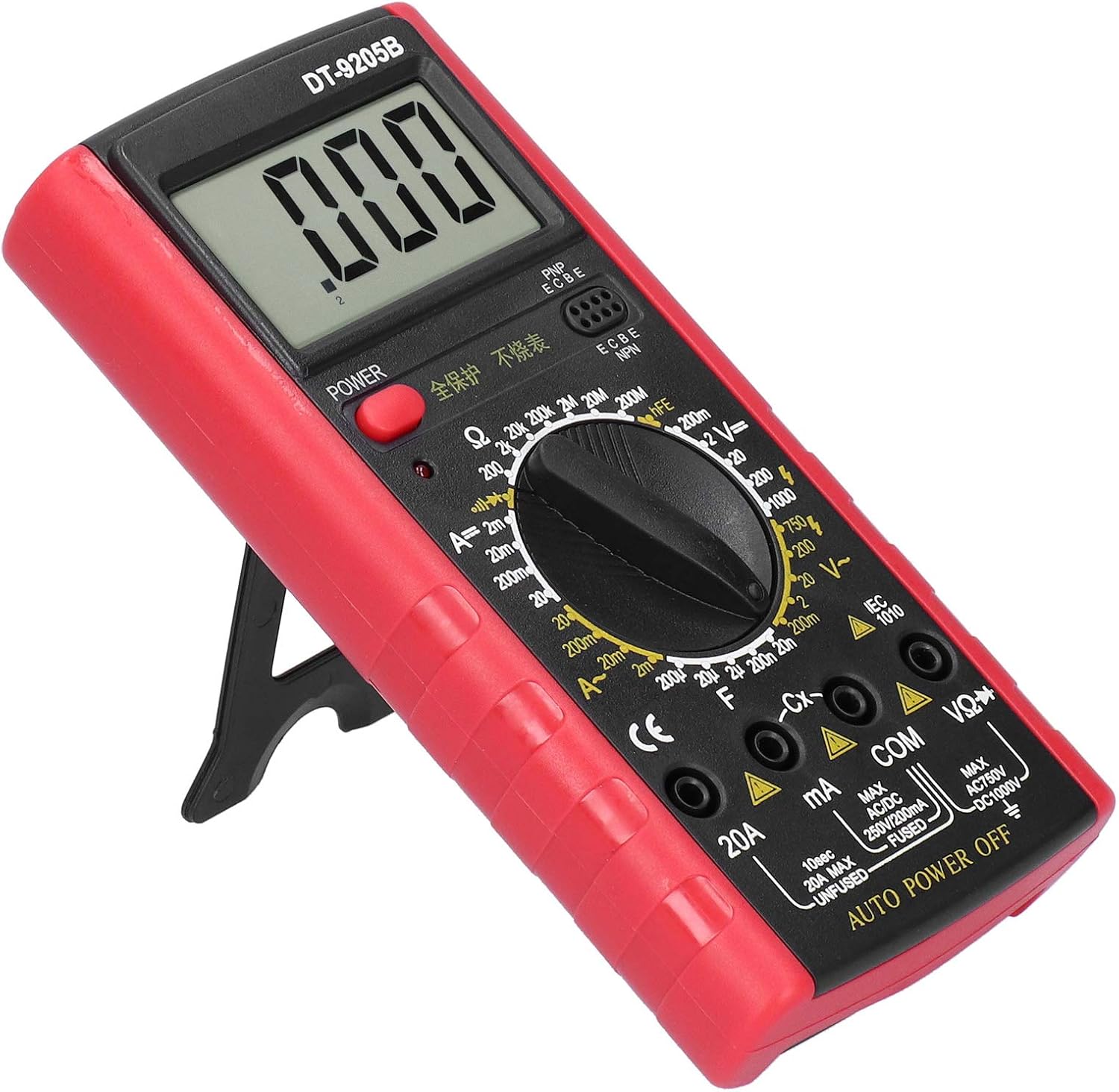
Figure 4.1: The DT9205B multimeter shown with its integrated kickstand for convenient viewing during setup and operation.
5. Operating Instructions
Before any measurement, ensure the multimeter is turned on and the test leads are correctly connected to the appropriate input jacks for the desired function.
5.1 Measuring DC Voltage (V=)
- Connect the red test lead to the 'VΩHz' jack and the black test lead to the 'COM' jack.
- Set the rotary switch to the desired 'V=' (DC Voltage) range. If the voltage is unknown, start with the highest range and decrease as needed.
- Connect the test leads in parallel across the component or circuit to be measured.
- Read the voltage value on the LCD display.
5.2 Measuring AC Voltage (V~)
- Connect the red test lead to the 'VΩHz' jack and the black test lead to the 'COM' jack.
- Set the rotary switch to the desired 'V~' (AC Voltage) range.
- Connect the test leads in parallel across the AC source or component.
- Read the voltage value on the LCD display.
5.3 Measuring DC Current (A=)
- IMPORTANT: Disconnect power to the circuit before connecting the multimeter.
- For mA range, connect the red test lead to the 'mA' jack. For 20A range, connect the red test lead to the '20A' jack. Connect the black test lead to the 'COM' jack.
- Set the rotary switch to the desired 'A=' (DC Current) range.
- Connect the multimeter in series with the circuit where current is to be measured.
- Apply power to the circuit and read the current value on the LCD display.

Figure 5.1: A technician utilizing the DT9205B multimeter for precise measurements on a circuit board.
5.4 Measuring Resistance (Ω)
- IMPORTANT: Ensure the circuit is de-energized and all capacitors are discharged.
- Connect the red test lead to the 'VΩHz' jack and the black test lead to the 'COM' jack.
- Set the rotary switch to the desired 'Ω' (Resistance) range.
- Connect the test leads across the component to be measured.
- Read the resistance value on the LCD display.
5.5 Continuity Test
- IMPORTANT: Ensure the circuit is de-energized.
- Connect the red test lead to the 'VΩHz' jack and the black test lead to the 'COM' jack.
- Set the rotary switch to the continuity symbol (often shared with diode or resistance).
- Touch the test leads across the component or wire. A continuous beep indicates a low-resistance path (continuity).

Figure 5.2: The DT9205B multimeter in use for diagnosing an automotive electrical system.
6. Maintenance
6.1 Cleaning
Wipe the case with a damp cloth and mild detergent. Do not use abrasives or solvents. Ensure the multimeter is completely dry before use.
6.2 Battery Replacement
Refer to Section 4.1 for detailed instructions on replacing the 6F22-9V battery. Replace the battery promptly when the low battery indicator appears on the display to maintain measurement accuracy.
6.3 Fuse Replacement
The current input jacks (mA, 20A) are protected by fuses. If the multimeter fails to measure current, the fuse may need replacement. Refer to the specifications for the correct fuse type and rating. Fuse replacement should only be performed by qualified personnel.
7. Troubleshooting
- No Display: Check if the power button is pressed. Ensure the battery is correctly installed and has sufficient charge. Replace the battery if necessary.
- Incorrect Readings: Verify the rotary switch is set to the correct function and range. Check test lead connections. Ensure the circuit is de-energized for resistance/continuity measurements.
- No Current Measurement: Check the fuse for the relevant current input jack (mA or 20A). Replace if blown. Ensure the multimeter is connected in series with the load.
- 'OL' or '1' on Display: This indicates an over-range condition. Select a higher range or verify the circuit is within the multimeter's measurement capabilities.
8. Specifications
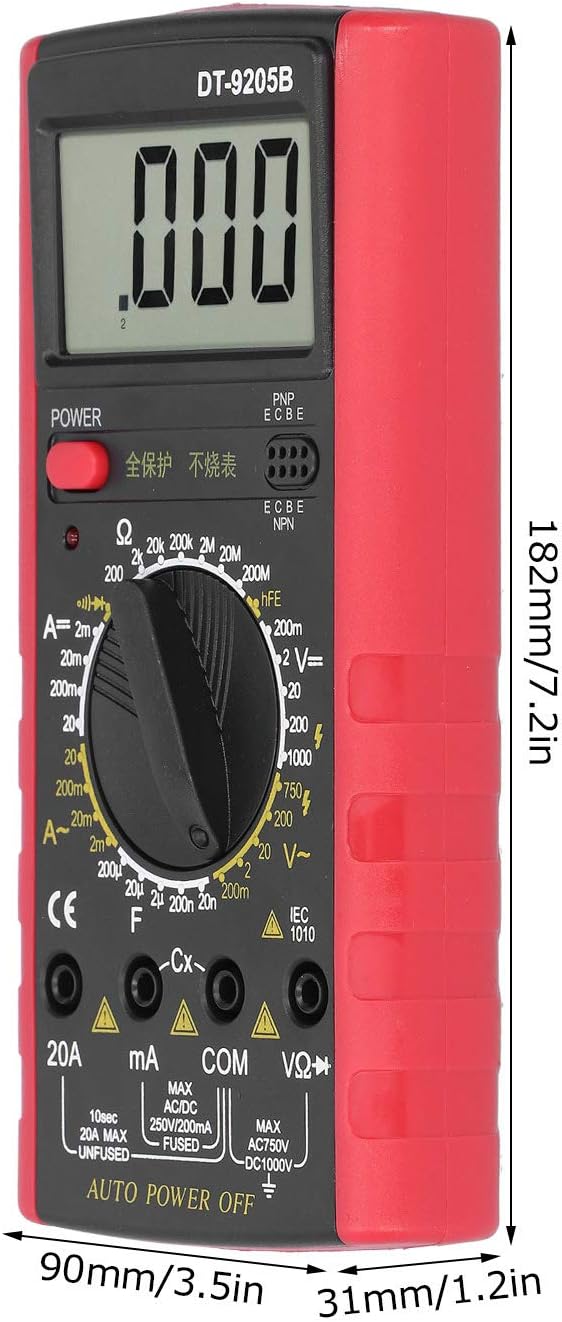
Figure 8.1: Dimensions of the DT9205B Digital Multimeter.
| Feature | Specification |
|---|---|
| Model | DT9205B |
| Material | ABS |
| Display | LCD, 25mm character height, Max 1999 |
| Over-Range Display | '1' |
| Working Temperature | 0℃ ~ 40℃ (32℉ ~ 104℉) |
| Storage Temperature | -10℃ ~ 50℃ (14℉ ~ 122℉) |
| Power Supply | 6F22-9V Battery (not included) |
| Dimensions (Approx.) | 182mm (7.2in) x 90mm (3.5in) x 31mm (1.2in) |
| Weight (Approx.) | 293 Grams (10.3 ounces) |
| Measurement Ranges | 32 ranges (Voltage, Current, Resistance, Capacitance, etc.) |
9. Warranty and Support
For warranty information or technical support regarding your LiebeWH DT9205B Digital Multimeter, please refer to the documentation included with your purchase or contact LiebeWH customer service directly. Keep your purchase receipt as proof of purchase.
For further assistance, you may visit the LiebeWH Store on Amazon.