StarNY MS6818
MS6818 Advanced Wire Tester Tracker Multi-Function Cable Detector
User Instruction Manual
Brand: StarNY | Model: MS6818
1. Introduction and Product Overview
The MS6818 Advanced Wire Tester Tracker is a multi-function cable detector designed for various applications in communication cable construction, electrical cable construction, building pipeline construction, telecommunications, and power supply circuits. It is an indispensable tool for maintenance personnel involved in electric line maintenance and construction.
This instrument is capable of:
- Detecting cables, electrical lines, and water/gas supply pipelines buried in walls or the earth.
- Detecting interruptions and short circuits in cables and electrical lines buried in walls or the earth.
- Detecting fuses and assigning current circuits.
- Detecting interruptions and short circuits in floor heating systems.
- Detecting sockets and distribution sockets that may have been accidentally covered by plastering.
- Locating open or shorted conduits under the floor.
2. Package Contents
Upon unpacking, please verify that all the following components are included:
- 1 x Receiver
- 1 x Transmitter
- 1 x Test Leads (Black & Red)
- 1 x Test Probe (Black & Red)
- 1 x Crocodile Clamps (Black & Red)
- 1 x Grounding Rod
- 1 x User Manual (this document)
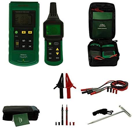
Figure 2.1: Overview of the MS6818 Cable Detector's complete package contents.
3. Product Features
The MS6818 is equipped with several advanced features to enhance its functionality and user experience:
- The transmitter integrates an AC/DC voltmeter function, capable of measuring 12 to 400V AC/DC voltage linearly.
- The transmitter's screen displays preset transmitting power, transmitted codes, its own battery energy, detected mains voltage, AC/DC status of detected mains voltage, and a warning symbol for mains voltage.
- The transmitter includes a self-inspection function to detect its working status and display it on the LCD screen for user reference.
- The sensitivity of the receiver can be adjusted manually or automatically.
- The receiver can sweep frequencies automatically.
- Both the transmitter and receiver can operate in mute mode.
- Additional transmitters are available for system expansion or to differentiate between multiple signals.
- The device is designed for compactness, durability, and portability.
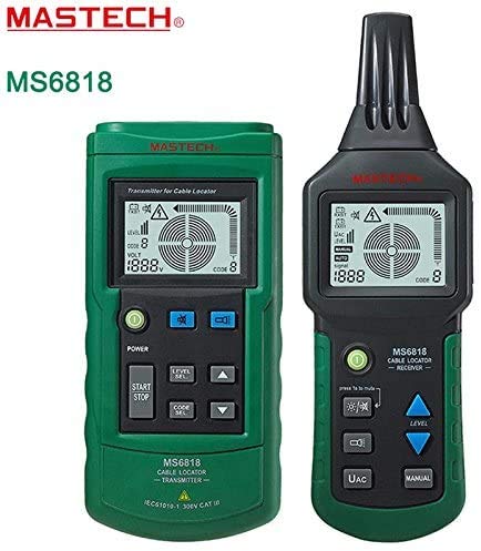
Figure 3.1: The MS6818 Transmitter (left) and Receiver (right) units.
4. Setup
4.1 Battery Installation
Both the transmitter and receiver units require batteries for operation. Locate the battery compartments on the rear of each unit. Insert the specified battery type, ensuring correct polarity. Secure the battery compartment covers.
4.2 Connecting Test Leads
Connect the red and black test leads to the corresponding input jacks on the transmitter. For direct connection to circuits, attach the crocodile clamps to the test leads. For probing, attach the test probes. Ensure all connections are secure before operation.
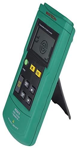
Figure 4.1: MS6818 Transmitter unit, showing controls and display.
5. Operating Instructions
5.1 Basic Operation
- Power On: Press the power button on both the transmitter and receiver units to turn them on.
- Transmitter Setup: Connect the transmitter to the circuit or cable to be tested using the appropriate test leads, probes, or clamps. The transmitter's display will show relevant information such as voltage and signal status.
- Receiver Operation: Use the receiver to trace the signal emitted by the transmitter. Adjust the receiver's sensitivity (manual or automatic) as needed to optimize detection.
- Mute Mode: For silent operation, activate the mute mode on both units if desired.
5.2 Specific Applications
5.2.1 Cable and Pipeline Detection
To detect buried cables or pipelines, connect the transmitter to one end of the cable/pipeline or to a nearby power source. Use the receiver to sweep the area where the cable/pipeline is suspected to be located. The receiver will indicate the presence and approximate path of the signal.
5.2.2 Interruption and Short Circuit Detection
For interruptions, connect the transmitter to one end of the cable. Trace the cable with the receiver until the signal disappears, indicating the point of interruption. For short circuits, the signal may become very strong or change characteristics near the short.
5.2.3 Fuse and Circuit Assignment
Connect the transmitter to an outlet or circuit. At the fuse box, use the receiver to identify which fuse corresponds to the active circuit by detecting the strongest signal.
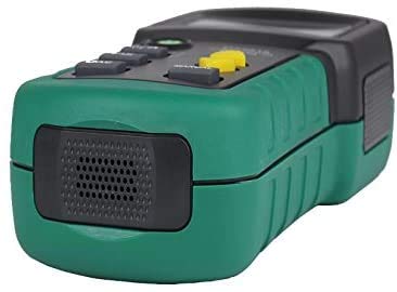
Figure 5.1: Side view of the MS6818 Receiver, showing its speaker for audible signal indication.
6. Maintenance
To ensure the longevity and accurate performance of your MS6818, follow these maintenance guidelines:
- Cleaning: Wipe the units with a soft, dry cloth. Do not use abrasive cleaners or solvents.
- Storage: Store the device in a cool, dry place, away from direct sunlight and extreme temperatures. If storing for extended periods, remove batteries to prevent leakage.
- Battery Replacement: Replace batteries promptly when the low battery indicator appears on the transmitter's display.
- Inspection: Periodically inspect test leads, probes, and clamps for any signs of wear or damage. Replace damaged accessories immediately.
7. Troubleshooting
If you encounter issues with your MS6818, refer to the following common problems and solutions:
| Problem | Possible Cause | Solution |
|---|---|---|
| No power/Unit does not turn on | Dead or incorrectly installed batteries. | Check battery polarity; replace with fresh batteries. |
| Weak or no signal detection | Transmitter not powered, incorrect connection, or receiver sensitivity too low. | Ensure transmitter is on and connected correctly. Increase receiver sensitivity. Check for signal interference. |
| Inaccurate readings on transmitter display | Poor connection to circuit or faulty test leads. | Verify secure connections. Inspect and replace test leads if damaged. |
| Receiver signal erratic or jumping | External electromagnetic interference or multiple signals. | Move away from strong electrical fields. Use additional transmitters to differentiate signals if applicable. |
8. Specifications
Key technical specifications for the MS6818 Advanced Wire Tester Tracker:
| Parameter | Value |
|---|---|
| Brand | StarNY |
| Model | MS6818 |
| Measurement Type | Voltmeter (integrated in transmitter) |
| Voltage Measurement Range (Transmitter) | 12 to 400V AC/DC |
| Power Source | Battery Powered |
| ASIN | B08T8KZGV2 |
| UPC | 765083462113 |
| Date First Available | January 17, 2021 |
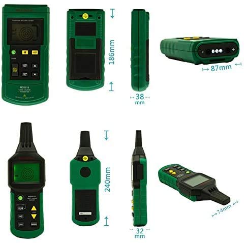
Figure 8.1: Dimensional overview of the MS6818 Transmitter and Receiver units.
9. Warranty and Support
For warranty information and technical support regarding your StarNY MS6818 Advanced Wire Tester Tracker, please refer to the warranty card included with your product or contact StarNY customer service directly. Details for contacting support are typically found on the manufacturer's official website or within the product packaging.
Please retain your proof of purchase for any warranty claims.