1. Introduction
This manual provides detailed instructions for the safe and effective operation of the StarNY HT118A Digital Multimeter. The HT118A is a handheld, battery-powered instrument designed for measuring AC/DC voltage, AC/DC current, resistance, capacitance, frequency, temperature, diode, and continuity. It features a clear LCD display with backlight, a flashlight, and non-contact voltage (NCV) detection.
2. Safety Information
Read all safety warnings and operating instructions before using this instrument. Failure to follow these instructions may result in electric shock, fire, or serious injury.
- Always ensure the multimeter is in the correct function and range before making measurements.
- Do not exceed the maximum input values for any range.
- Exercise extreme caution when working with voltages above 30V AC RMS, 42V peak, or 60V DC. These voltages pose a shock hazard.
- Inspect test leads for damaged insulation or exposed metal before use. Replace if damaged.
- Do not use the multimeter if it appears damaged or if it is not operating properly.
- Remove test leads from the circuit before changing functions.
- Replace batteries when the low battery indicator appears to ensure accurate readings.
- Adhere to local and national safety codes.
3. Product Overview
The StarNY HT118A Digital Multimeter is designed for ease of use and durability. Familiarize yourself with its components:
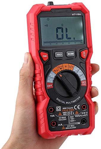
Figure 3.1: Labeled diagram of the HT118A Multimeter showing the NCV probe, flashlight, LCD display, function keys, function knob, and input sockets.
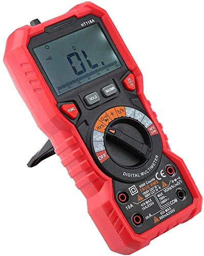
Figure 3.2: Front view of the StarNY HT118A Digital Multimeter, displaying its robust red and black casing and clear LCD screen.
3.1. Components
- LCD Display: Shows measurement readings, units, and function indicators. Features dual-color backlight.
- Function Knob: Rotary switch to select measurement functions (e.g., V~, V-, A~, A-, Ohm, Cap, Hz, Temp, Diode, Continuity, NCV, Live).
- Function Keys: Buttons for specific operations like FUNC (mode selection), HOLD (data hold), MAX/MIN (maximum/minimum value), and backlight/flashlight activation.
- Input Sockets:
- COM: Common input for all measurements (black test lead).
- VΩHz: Input for voltage, resistance, frequency, capacitance, diode, and continuity measurements (red test lead).
- mA/µA: Input for milliampere and microampere current measurements (red test lead).
- 10A: Input for 10 Ampere current measurements (red test lead).
- NCV Probe: Located at the top for non-contact voltage detection.
- Flashlight: Integrated light for illuminating work areas.
4. Setup
4.1. Battery Installation
The HT118A Multimeter requires two (2) 1.5V AAA batteries (not included) for operation.
- Ensure the multimeter is turned OFF.
- Locate the battery compartment cover on the back of the unit.
- Use a screwdriver to loosen the screw(s) on the battery cover.
- Remove the cover.
- Insert two new 1.5V AAA batteries, observing the correct polarity (+ and -).
- Replace the battery cover and secure it with the screw(s).
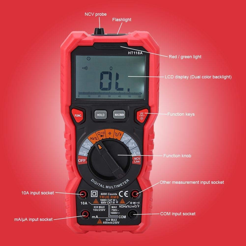
Figure 4.1: Rear view of the HT118A Multimeter, showing the battery compartment cover and kickstand.
Note: When the low battery indicator appears on the display, replace the batteries promptly to maintain measurement accuracy.
5. Operating Instructions
Before making any measurements, ensure the test leads are properly connected and the function knob is set to the desired measurement type.
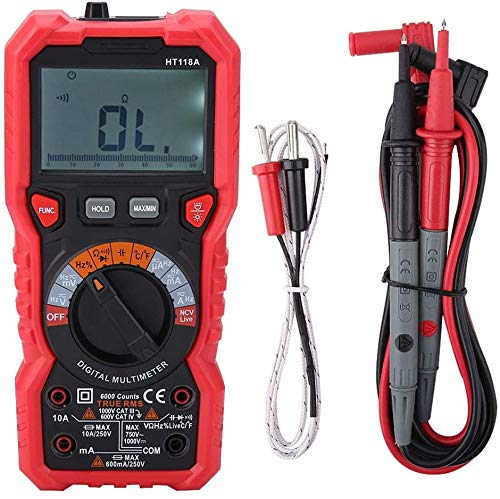
Figure 5.1: The HT118A Multimeter shown with its included test leads and temperature probe, ready for various measurements.
5.1. General Operation
- Power ON/OFF: Rotate the function knob from "OFF" to any desired measurement function to turn the meter ON. Rotate back to "OFF" to power OFF. The meter also features an auto power-off function after 15 minutes of inactivity.
- Function (FUNC) Button: Used to switch between different modes within a single knob position (e.g., AC/DC voltage, Diode/Continuity, Celsius/Fahrenheit).
- HOLD Button: Press to freeze the current reading on the display. Press again to release.
- MAX/MIN Button: Press to display the maximum or minimum measured value. Press again to cycle through MAX, MIN, and current readings.
- Backlight/Flashlight Button: Press briefly to turn the LCD backlight ON/OFF. Press and hold to turn the flashlight ON/OFF.
5.2. Measuring DC Voltage (V-)
- Insert the black test lead into the COM jack and the red test lead into the VΩHz jack.
- Rotate the function knob to the V- position.
- Connect the test leads across the DC voltage source to be measured.
- Read the voltage value on the display.
5.3. Measuring AC Voltage (V~)
- Insert the black test lead into the COM jack and the red test lead into the VΩHz jack.
- Rotate the function knob to the V~ position.
- Connect the test leads across the AC voltage source to be measured.
- Read the voltage value on the display.
5.4. Measuring DC Current (A-, mA-, µA-)
Caution: Never connect the test leads in parallel to a voltage source when measuring current. This can damage the meter and the circuit.
- Determine the expected current range. For currents up to 600mA, use the mA/µA jack. For currents up to 10A, use the 10A jack.
- Insert the black test lead into the COM jack. Insert the red test lead into the appropriate current jack (mA/µA or 10A).
- Rotate the function knob to the corresponding A-, mA-, or µA- position.
- Open the circuit where current is to be measured and connect the multimeter in series with the load.
- Read the current value on the display.
5.5. Measuring AC Current (A~, mA~, µA~)
Caution: Never connect the test leads in parallel to a voltage source when measuring current. This can damage the meter and the circuit.
- Determine the expected current range. For currents up to 600mA, use the mA/µA jack. For currents up to 10A, use the 10A jack.
- Insert the black test lead into the COM jack. Insert the red test lead into the appropriate current jack (mA/µA or 10A).
- Rotate the function knob to the corresponding A~, mA~, or µA~ position.
- Open the circuit where current is to be measured and connect the multimeter in series with the load.
- Read the current value on the display.
5.6. Measuring Resistance (Ω)
- Insert the black test lead into the COM jack and the red test lead into the VΩHz jack.
- Rotate the function knob to the Ω position.
- Ensure the circuit or component to be measured is de-energized.
- Connect the test leads across the component.
- Read the resistance value on the display.
5.7. Measuring Capacitance (F)
- Insert the black test lead into the COM jack and the red test lead into the VΩHz jack.
- Rotate the function knob to the Capacitance position (often shared with Hz). Press FUNC if necessary to select capacitance.
- Ensure the capacitor is fully discharged before measurement to prevent damage to the meter.
- Connect the test leads across the capacitor terminals.
- Read the capacitance value on the display.
5.8. Measuring Frequency/Duty Cycle (Hz/%)
- Insert the black test lead into the COM jack and the red test lead into the VΩHz jack.
- Rotate the function knob to the Hz/% position (often shared with Capacitance). Press FUNC if necessary to select frequency or duty cycle.
- Connect the test leads across the signal source.
- Read the frequency or duty cycle value on the display.
5.9. Measuring Temperature (°C/°F)
- Insert the temperature probe into the COM and VΩHz jacks, observing polarity.
- Rotate the function knob to the Temp position. Press FUNC to switch between Celsius and Fahrenheit.
- Place the tip of the temperature probe on or near the object whose temperature is to be measured.
- Read the temperature value on the display.
5.10. Diode Test
- Insert the black test lead into the COM jack and the red test lead into the VΩHz jack.
- Rotate the function knob to the Diode/Continuity position. Press FUNC to select Diode Test.
- Connect the red test lead to the anode and the black test lead to the cathode of the diode. The display will show the forward voltage drop.
- Reverse the test leads. The display should show "OL" (Open Line) for a good diode.
5.11. Continuity Test
- Insert the black test lead into the COM jack and the red test lead into the VΩHz jack.
- Rotate the function knob to the Diode/Continuity position. Press FUNC to select Continuity Test (indicated by a buzzer symbol).
- Connect the test leads across the circuit or component to be tested.
- If the resistance is below approximately 50Ω, the buzzer will sound, indicating continuity.
5.12. Non-Contact Voltage (NCV) Detection
- Rotate the function knob to the NCV position.
- Move the NCV probe (top of the meter) close to the conductor or outlet.
- If AC voltage is detected, the meter will beep and the red/green light will illuminate, with the frequency of beeps and light increasing with voltage strength.
5.13. Live Wire Test
- Rotate the function knob to the Live position.
- Insert the red test lead into the VΩHz jack. The black test lead is not used for this function.
- Touch the red test lead to the suspected live wire.
- If a live wire is detected, the meter will beep and the red/green light will illuminate.
6. Maintenance
6.1. Cleaning
Wipe the case with a damp cloth and mild detergent. Do not use abrasives or solvents. Ensure the meter is completely dry before use.
6.2. Battery Replacement
Refer to Section 4.1 for instructions on replacing the batteries. Always replace both batteries at the same time with new ones of the same type (2 x 1.5V AAA).
6.3. Fuse Replacement
The HT118A Multimeter is equipped with internal fuses to protect against overcurrent. If the current measurement function stops working, the fuse may need replacement. Fuse replacement should only be performed by qualified personnel. Refer to the specifications for fuse ratings.
7. Troubleshooting
- Meter does not power on: Check battery installation and ensure batteries are not depleted. Replace if necessary.
- "OL" (Overload) displayed: The measured value exceeds the selected range. Select a higher range or ensure the circuit is within the meter's capabilities.
- Inaccurate readings: Check battery level. Ensure test leads are properly connected and not damaged. Verify the correct function and range are selected.
- No continuity beep: Ensure the continuity function is selected. Check test leads for open circuits.
- No current measurement: Check if the fuse is blown. Ensure the meter is connected in series with the load.
8. Specifications
| Measurement | Range | Resolution | Accuracy |
|---|---|---|---|
| DC Voltage | |||
| 600mV | 0.1mV | (0.5% reading+3) | |
| 6V | 0.001V | ||
| 60V | 0.01V | ||
| 600V | 0.1V | ||
| 1000V | 1V | ||
| AC Voltage | |||
| 600mV | 0.1mV | (0.8% reading+5) | |
| 6V | 0.001V | ||
| 60V | 0.01V | ||
| 600V | 0.1V | ||
| 750V | 1V | ||
| DC Current | |||
| 600µA | 0.1µA | (1.2% reading+3) | |
| 6000µA | 1µA | ||
| 60mA | 0.01mA | ||
| 600mA | 0.1mA | ||
| 10A | 0.01A | ||
| AC Current | |||
| 600µA | 0.1µA | (1.5% reading+3) | |
| 6000µA | 1µA | ||
| 60mA | 0.01mA | ||
| 600mA | 0.1mA | ||
| 10A | 0.01A | ||
| Resistance | |||
| 600Ω | 0.1Ω | (1.0% reading+3) | |
| 6kΩ | 0.001kΩ | ||
| 60kΩ | 0.01kΩ | ||
| 600kΩ | 0.1kΩ | ||
| 6MΩ | 0.001MΩ | (1.5% reading+3) | |
| 60MΩ | 0.01MΩ | ||
| Capacitance | |||
| 10nF | 0.001nF | (4.0% reading+5) | |
| 100nF | 0.01nF | ||
| 1000nF | 0.1nF | ||
| 10µF | 0.001µF | ||
| 100µF | 0.01µF | ||
| 1000µF | 0.1µF | ||
| 10mF | 0.001mF | (5.0% reading+5) | |
| 100mF | 0.01mF | ||
| Frequency/Duty Cycle | |||
| 10Hz | 0.001Hz | (1.0% reading+3) | |
| 100Hz | 0.01Hz | ||
| 1000Hz | 0.1Hz | ||
| 10kHz | 0.001kHz | ||
| 100kHz | 0.01kHz | ||
| 1000kHz | 0.1kHz | ||
| 10MHz | 0.001MHz | (3.0% reading+3) | |
| Duty Cycle | 1~99% | 0.1% | |
| Temperature | |||
| Celsius | -20~0°C | 1°C | 5.0% reading or 3°C |
| 0~400°C | 1°C | 1.0% reading or 2°C | |
| 400~1000°C | 1°C | 2.0% reading | |
| Fahrenheit | -4~32°F | 1°F | 5.0% reading or 6°F |
| 32~752°F | 1°F | 1.0% reading or 4°F | |
| 752~1832°F | 1°F | 2.0% reading | |
| General Parameters | |||
| Model | HT118A | ||
| Material | Plastic | ||
| Color | Red + Black | ||
| Sampling Rate | About 3 times/second | ||
| Battery Type | 2 x 1.5V AAA batteries (NOT included) | ||
| Working Environment | 0~40°C, <80% RH | ||
| Storage Environment | -10~60°C, <70% RH | ||
| Display | 6000 counts | ||
| Auto Power Off | 15min | ||
| Over Range Indication | "OL" | ||
| Low Battery Indication | Yes | ||
| Diode Test | Yes | ||
| Continuity Test | Yes | ||
| NCV | Yes | ||
| Live Test | Yes | ||
| High Voltage Prompt | >80V or >1A | ||
| Data Hold | Yes | ||
| Max/Min | Yes | ||
| Backlight | Yes | ||
| Flashlight | Yes | ||
9. Warranty and Support
For warranty information and technical support, please contact the seller or manufacturer directly. Keep your purchase receipt as proof of purchase.
Manufacturer: StarNY
UPC: 765083463172