1. Introduction
This manual provides detailed instructions for the installation, operation, and maintenance of your Audiobank P1502 2-Channel Car Amplifier and the included 8-gauge installation wiring kit. Please read this manual thoroughly before attempting installation or operation to ensure proper use and to prevent damage to the unit or your vehicle's electrical system.

Figure 1.1: Audiobank P1502 2-Channel Car Amplifier. This image shows the top view of the silver-colored amplifier with the 'AUDIOBANK' logo and '1500WATTS' text.
2. Safety Information
Always observe the following safety precautions during installation and operation:
- Disconnect the vehicle's negative battery terminal before starting any electrical work.
- Ensure all wiring is properly insulated to prevent short circuits.
- Mount the amplifier securely to prevent it from becoming a projectile in an accident.
- Avoid mounting the amplifier in areas exposed to direct sunlight, excessive heat, or moisture.
- Use appropriate gauge wiring as specified in this manual and the installation kit.
- Do not bypass or modify the included fuse.
- If you are unsure about any part of the installation, consult a professional car audio installer.
3. Package Contents
Verify that all items are present in your package:
- Audiobank P1502 2-Channel Car Amplifier
- High Quality Thick 17 Feet 8 Gauge Power Cable
- Premium 3 Feet 8 Gauge Ground Cable
- Inline AGU Fuse Holder & 60A Fuse
- True Sound 17 Feet Double Shielded RCA Cable
- High Quality 17 Feet / 18 Gauge Turn-On Cable
- 20 Feet / 16 Gauge Speaker Wire
- All necessary accessories and terminals for installation

Figure 3.1: Components of the 8-gauge car amplifier installation wiring kit. This image displays various cables (power, ground, RCA, speaker, remote), an AGU fuse holder with a fuse, and assorted terminals.
4. Setup and Installation
Proper installation is crucial for optimal performance and safety. Follow these steps carefully:
4.1. Mounting the Amplifier
- Choose a secure location that is dry, well-ventilated, and away from direct heat sources. Common locations include under a seat, in the trunk, or behind a panel.
- Ensure there is sufficient airflow around the amplifier's heatsink to prevent overheating.
- Use the provided mounting hardware to firmly secure the amplifier to a solid surface in your vehicle.
4.2. Wiring Connections
Refer to the diagrams below for proper wiring. Always ensure the vehicle's battery is disconnected before making any connections.
4.2.1. Power Connections
- Ground (GND): Connect the 3-foot 8-gauge ground cable from the amplifier's GND terminal to a clean, unpainted metal surface on the vehicle's chassis. Ensure a solid, low-resistance connection.
- Remote (REM): Connect the 18-gauge turn-on cable from the amplifier's REM terminal to the remote turn-on output of your head unit. This wire signals the amplifier to turn on and off with your stereo.
- +12V: Connect the 17-foot 8-gauge power cable from the amplifier's +12V terminal to the positive (+) terminal of your vehicle's battery. Install the inline AGU fuse holder with the 60A fuse as close to the battery as possible (within 18 inches) to protect the power cable.

Figure 4.1: Rear view of the Audiobank P1502 amplifier showing the power input terminals (GND, REM, +12V) and speaker output terminals (CH1, CH2, Bridge). The fuse slots are also visible.

Figure 4.2: The 17-foot 8-gauge red power cable included in the kit.
4.2.2. Audio Input Connections
- Connect the 17-foot double-shielded RCA cable from the RCA outputs of your head unit to the RCA INPUTs (CH1 and CH2) on the amplifier.
- Alternatively, if your head unit does not have RCA outputs, use the speaker-level inputs (if applicable) by connecting the speaker wires from your head unit to the amplifier's speaker-level input terminals.
4.2.3. Speaker Output Connections
- Connect your speakers to the amplifier's speaker output terminals using the 16-gauge speaker wire.
- Ensure correct polarity (+ to + and - to -) for each speaker.
- For 2-channel stereo operation, connect one speaker to CH1 and another to CH2.
- For bridged (mono) operation, connect a single subwoofer or speaker to the BRIDGE terminals (typically CH1+ and CH2- or as marked on the amplifier). The P1502 supports tri-mode operation.
- The amplifier is 2 Ohm stable, allowing for flexible speaker configurations.

Figure 4.3: The 20-foot 16-gauge red and black speaker wire included in the kit.
5. Operating Instructions
Once installed, adjust the amplifier settings for optimal sound performance.
5.1. Amplifier Controls
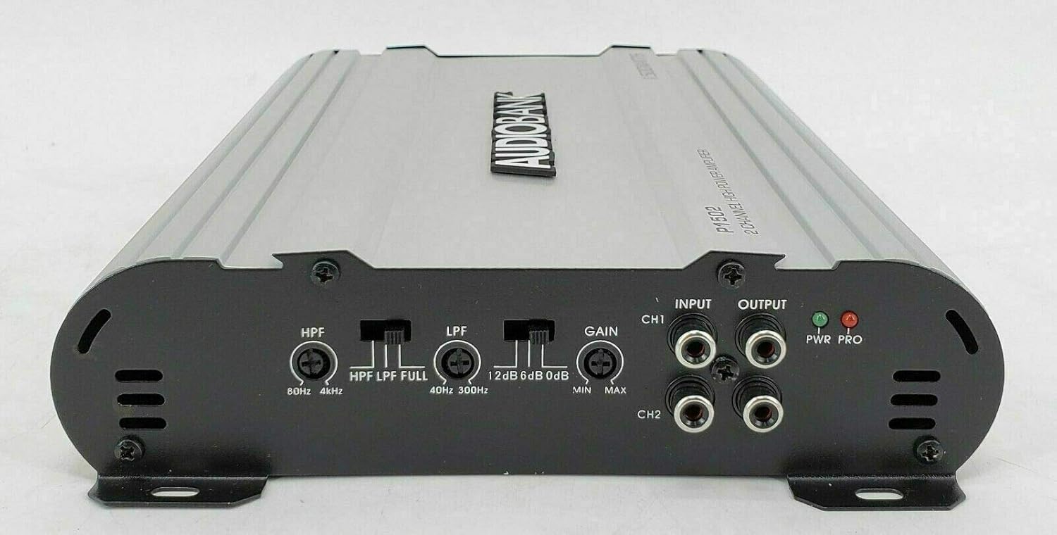
Figure 5.1: Front view of the Audiobank P1502 amplifier showing the control panel with HPF, LPF, Gain, Input, Output, and LED indicators.
- Input Gain Control (GAIN): This control matches the amplifier's input sensitivity to the output of your head unit. Start with the gain at minimum (MIN) and slowly increase it until you hear distortion, then back off slightly.
- Low Pass Crossover (LPF): Adjusts the frequency range (40Hz-300Hz) for signals passed to subwoofers. Only frequencies below the set point will be amplified.
- High Pass Crossover (HPF): Adjusts the frequency range (80Hz-4kHz) for signals passed to full-range speakers. Only frequencies above the set point will be amplified.
- Bass Boost: Provides an adjustable bass enhancement from 0 to +12dB. Use sparingly to avoid distortion.
5.2. LED Indicators
- PWR (Power) LED: Illuminates green when the amplifier is powered on and operating normally.
- PRO (Protection) LED: Illuminates red when the amplifier enters protection mode due to a fault (e.g., overheating, short circuit, low impedance). If this LED lights up, turn off your system immediately and troubleshoot the issue.
6. Maintenance
To ensure the longevity and performance of your amplifier:
- Regularly check all wiring connections for tightness and corrosion.
- Keep the amplifier's heatsink clean and free from dust or debris to maintain proper cooling. Use a soft, dry cloth for cleaning.
- Ensure adequate ventilation around the amplifier at all times.
- Do not expose the amplifier to liquids or excessive moisture.
7. Troubleshooting
If you experience issues with your amplifier, consult the following table before seeking professional service:
| Problem | Possible Cause | Solution |
|---|---|---|
| No Power (PWR LED off) | Blown fuse, poor power/ground connection, no remote signal. | Check the inline fuse and replace if necessary. Verify +12V, GND, and REM connections. Ensure head unit is on. |
| Protection Mode (PRO LED on) | Overheating, speaker short circuit, impedance too low. | Allow amplifier to cool. Check speaker wiring for shorts. Verify speaker impedance is within acceptable limits (2 Ohm stable). |
| No Sound | No input signal, incorrect gain setting, speaker wires disconnected. | Check RCA or speaker-level input connections. Adjust gain. Verify speaker connections. |
| Distorted Sound | Gain set too high, improper crossover settings, poor ground. | Reduce gain. Adjust LPF/HPF settings. Check ground connection. |
8. Specifications
| Feature | Specification |
|---|---|
| Model Number | P1502 |
| Number of Channels | 2 |
| Maximum Output Power | 1500W Peak |
| Power MAX (2 Ohms) | 750W x 2 |
| Power RMS (4 Ohms) | 175W x 2 |
| Bridged Power (4 Ohms) | 1500W x 1 |
| S/N Ratio | 99dB |
| Low Pass Crossover (Variable) | 40Hz-300Hz |
| High Pass Crossover | 80Hz-4kHz |
| Bass Boost (Variable) | 0 - +12dB |
| Tri-mode Operation | Yes |
| Inputs | Line Level & Speaker Level |
| Frequency Response | 20Hz ~ 22kHz |
| THD (at RMS Output) | 0.01% |
| Channel Separation | 90dB |
| Damping Factor | 125+ |
| Fuse Rating | 20A x 2 |
| Dimensions (W x H x D) | 8 x 2 x 11.38 inches |
| Minimum Supply Voltage | 12 Volts |
| Mounting Type | Surface Mount |
| Specification Met | FCC |
9. Warranty and Support
For warranty information and technical support, please refer to the documentation provided with your purchase or contact Audiobank customer service directly. Keep your proof of purchase for warranty claims.