sara-u ZK-4KX
Sara-u ZK-4KX CNC DC-DC Buck-Boost Converter Module User Manual
Model: ZK-4KX
1. Product Overview
The Sara-u ZK-4KX is a versatile CNC DC-DC Buck-Boost Converter Module designed for precise voltage regulation. It features constant current (CC) and constant voltage (CV) capabilities, allowing for flexible power supply applications. This module is equipped with multiple software protection mechanisms to ensure safe and stable operation, with adjustable protection thresholds. Its compact design and efficient heat dissipation make it suitable for various electronic projects requiring reliable power conversion.
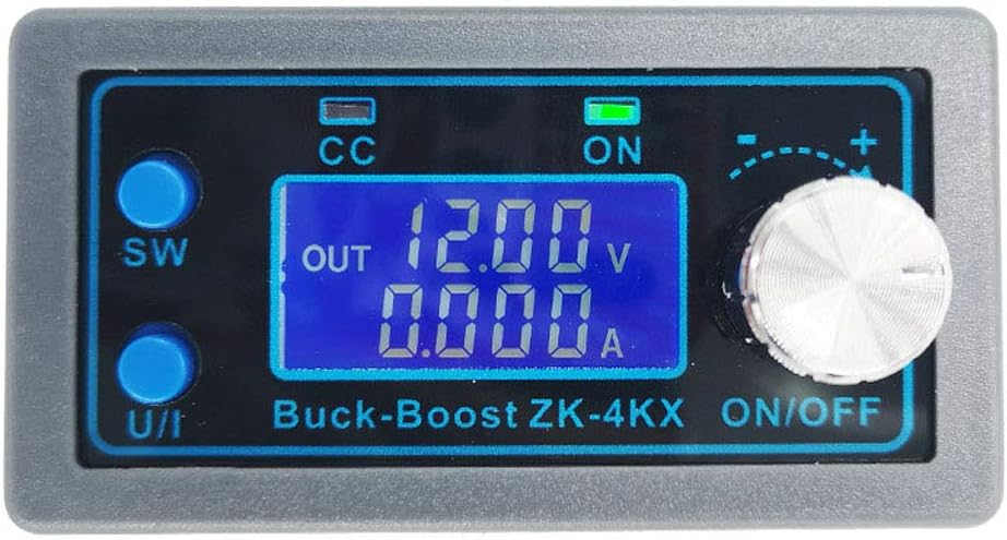
Figure 1: Front view of the ZK-4KX module, displaying its LCD screen, control buttons (SW, U/I), and rotary encoder.
2. Key Features
- Wide Input/Output Range: Input voltage 5.0-30V, Output voltage 0.5-30V.
- High Current Capability: Stable operation at 3A, up to 4A with enhanced heat dissipation.
- CNC Adjustment: Precise and fast adjustment of output voltage and current.
- Comprehensive Display: Large LCD shows input/output voltage, output current, output power, output capacity, and output time.
- Multiple Protection Mechanisms: Includes input anti-reverse connection, output anti-reverse irrigation, undervoltage, overvoltage, overcurrent, overpower, overtemperature, timeout, and super capacity protection.
- High Conversion Efficiency: Approximately 88%.
- Soft Start Function: Ensures stable startup (may vary with high power/load).
- Thickened Radiator Fins: Aids in quick heat dissipation for extended service life.
3. Specifications
| Parameter | Value |
|---|---|
| Model | ZK-4KX |
| Material | Fiber glass board, Electronic component |
| Dimensions (L x W x H) | 7.9 x 4.3 x 2.6 cm (3.11 x 1.69 x 1.02 in) |
| Input Voltage | 5.0V - 30V |
| Output Voltage | 0.5V - 30V |
| Output Current | 3A (stable long-term), 4A (with enhanced heat dissipation) |
| Output Power | 35W (natural heat dissipation), 50W (strengthened heat dissipation) |
| Voltage Display Resolution | 0.01V |
| Current Display Resolution | 0.001A |
| Conversion Efficiency | ~88% |
| Operating Frequency | 180KHz |

Figure 2: Physical dimensions of the ZK-4KX module.
4. Setup and Installation
The ZK-4KX module requires proper wiring for safe and effective operation. Ensure all connections are secure before applying power.
4.1 Wiring Connections
Identify the input and output terminals on the module. The terminals are clearly labeled for positive and negative connections.
- IN+: Positive input from your power source (5.0V - 30V DC).
- IN-: Negative input from your power source.
- OUT+: Positive output to your load (0.5V - 30V DC).
- OUT-: Negative output to your load.

Figure 3: Rear view of the module with clearly marked input and output terminals.
4.2 Initial Power-Up
After connecting the input power source and the load, apply power. The LCD display will illuminate, showing the current operating parameters. The module is designed with input anti-reverse connection protection, preventing damage if input polarity is accidentally reversed.
5. Operating Instructions
The ZK-4KX module features a user-friendly interface with an LCD display, two buttons (SW, U/I), and a rotary encoder for parameter adjustment.

Figure 4: Front panel components and indicators.
5.1 Button Functions
| Key | Normal Interface | Regulating Voltage and Constant Current Interface | Set Parameters Interface |
|---|---|---|---|
| SW Button | Short press: Switch display between Current (A), Power (W), Capacity (Ah), Time (h). Long press: Switch display between Input Voltage and Output Voltage. | (Not applicable) | Short press: Toggle the parameter to be set. Long press: (Not applicable) |
| U/I Button | Short press: Enter the interface for regulating voltage and constant current. Long press: Enter the interface for setting parameters. | Short press: Switch between regulating voltage value, regulating constant current value, and exiting regulating mode. Long press: (Not applicable) | Short press: (Not applicable) Long press: Exit the setting parameters interface and return to the normal interface. |
| Rotary Encoder | Short press: Toggle output ON/OFF. Long press: (Not applicable) Left rotation: Output voltage decreases. Right rotation: Output voltage increases. | Short press: Adjust the parameter shift accordingly. Long press: (Not applicable) Left rotation: The corresponding bit of adjustment parameter decreases. Right rotation: The corresponding bit of adjustment parameter increases. | Short press: Adjust the parameter shift accordingly. Long press: Turn OFF if parameters allow. Left rotation: The corresponding bit of adjustment parameter decreases. Right rotation: The corresponding bit of adjustment parameter increases. |
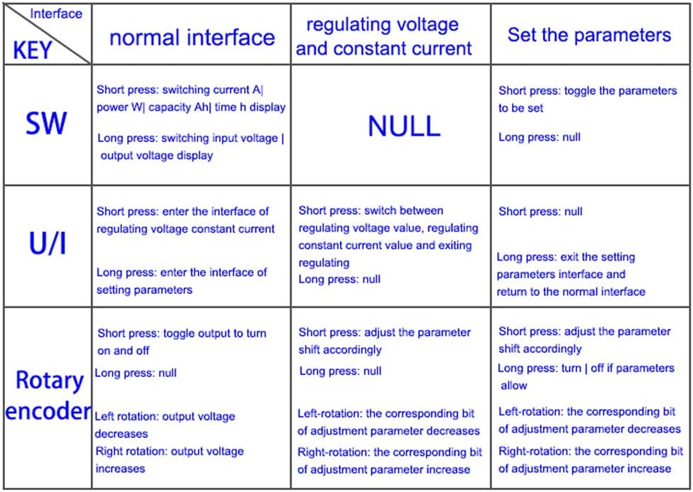
Figure 5: Detailed function table for buttons and rotary encoder.
5.2 Setting Parameters
To enter the parameter setting interface, long press the U/I button. Use the SW button to cycle through the parameters you wish to adjust. Use the Rotary Encoder to change the values. Long press the U/I button again to exit the setting interface.

Figure 6: Examples of parameter setting interfaces on the LCD.
6. Protection Mechanisms
The ZK-4KX module incorporates several adjustable protection mechanisms to safeguard itself and connected devices. When a working parameter exceeds its set threshold, the output will automatically shut down.
- Input Anti-reverse Connection: Prevents damage from reversed input polarity.
- Output Anti-reverse Irrigation: No additional anti-reverse irrigation diode is needed when charging batteries.
- Input Undervoltage Protection (LUP): Adjustable from 4.8V to 30V (default 4.8V).
- Output Overvoltage Protection (OUP): Adjustable from 0.5V to 31V (default 31V).
- Output Overcurrent Protection (OCP): Adjustable from 0A to 4.1A (default 4.1A).
- Overpower Protection (OPP): Adjustable from 0W to 50W (default 50W).
- Overtemperature Protection (OTP): Adjustable from 80°C to 110°C (default 110°C).
- Timeout Protection (OHP): Adjustable from 0 to 100 hours (default OFF).
- Super Capacity Protection (OAP): Adjustable from 0 to 60AH (default OFF).
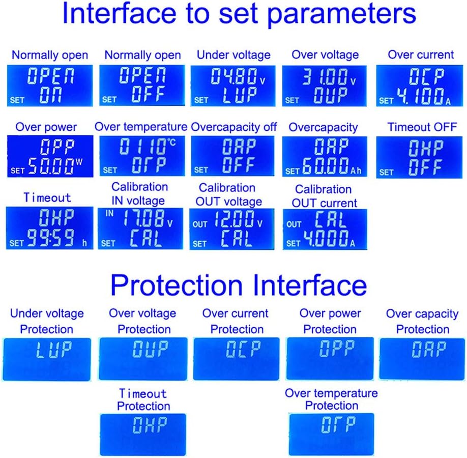
Figure 7: Examples of protection interface displays.
7. Maintenance
To ensure the longevity and optimal performance of your ZK-4KX module, follow these general maintenance guidelines:
- Keep Clean: Regularly clean the module to prevent dust accumulation, especially on the heat sink and ventilation areas. Use a soft, dry cloth or compressed air.
- Environmental Conditions: Operate the module within its specified temperature and humidity ranges. Avoid exposure to moisture, extreme temperatures, and corrosive environments.
- Secure Connections: Periodically check all wiring connections to ensure they are tight and free from corrosion. Loose connections can lead to unstable operation or damage.
- Heat Dissipation: Ensure adequate airflow around the module, especially during high-power operation, to allow the thickened radiator fins to dissipate heat effectively.
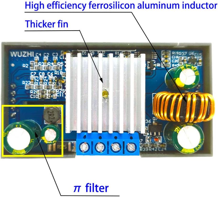
Figure 8: Internal components showing the heat sink and filter for efficient operation.
8. Troubleshooting
If you encounter issues with your ZK-4KX module, consider the following common troubleshooting steps:
- No Display/No Output:
- Check input power supply: Ensure it is within the 5.0V-30V range and properly connected (IN+, IN-).
- Verify output connections: Ensure the load is correctly connected to OUT+ and OUT-.
- Check for protection activation: The module may have automatically shut down due to an activated protection mechanism (e.g., overvoltage, overcurrent, undervoltage). Check the display for error codes or indicators.
- Output Voltage/Current Not Stable:
- Ensure connections are secure and free from loose wires.
- Check the load: Ensure the load is not drawing more current or power than the module's capacity (3A/35W natural, 4A/50W enhanced).
- Verify input power stability: Fluctuations in input power can affect output stability.
- Module Overheating:
- Ensure adequate ventilation around the module.
- Reduce the load if operating near maximum power (50W).
- Check if the overtemperature protection (OTP) threshold is set too low.
- Parameters Cannot Be Adjusted:
- Ensure you are in the correct parameter setting interface (long press U/I button).
- Follow the button function table (Figure 5) for correct operation.
9. Package Contents
The standard package for the Sara-u ZK-4KX DC-DC Buck-Boost Converter Module includes:
- 1 x ZK-4KX DC-DC Buck-Boost Converter Module
Note: No retail package is included.
10. Warranty and Support
For warranty information or technical support regarding your Sara-u ZK-4KX module, please refer to the seller or the point of purchase. Keep your purchase receipt as proof of purchase.
For further assistance, you may contact the manufacturer, Sara-u, through their official channels if available.
Ask a question about this manual
Ask about setup, troubleshooting, compatibility, parts, safety, or missing instructions. Manuals+ will review the question and use this page’s manual context to help answer it.