1. Introduction
This manual provides instructions for the installation, operation, and maintenance of the Thincol 36V-48V Universal Electric Bicycle DC Motor Controller with LCD Display and Throttle Handle. This system is designed for electric bicycles, scooters, and tricycles, offering universal voltage compatibility and real-time voltage display for accurate charge monitoring.
2. Package Contents
Verify that all components listed below are present in your package:
- 1 x Controller
- 1 x Meter (LCD Display)
- 1 x Half throttle
- 1 x Throttle grip
- 1 x Clip
- 2 x Key

Figure 2.1: Overview of the Thincol Motor Brushless Controller kit components, including the controller unit, LCD display, throttle handles, and keys.
3. Product Specifications
| Specification | Value |
|---|---|
| Brand | Thincol |
| Model | Thincolbdq7gh09pf |
| Voltage Compatibility | 36V-48V (Universal) |
| Rated Power | 250W/350W |
| Material | Blend |
| Weight | Approx. 611g |
4. Installation
4.1 Component Identification
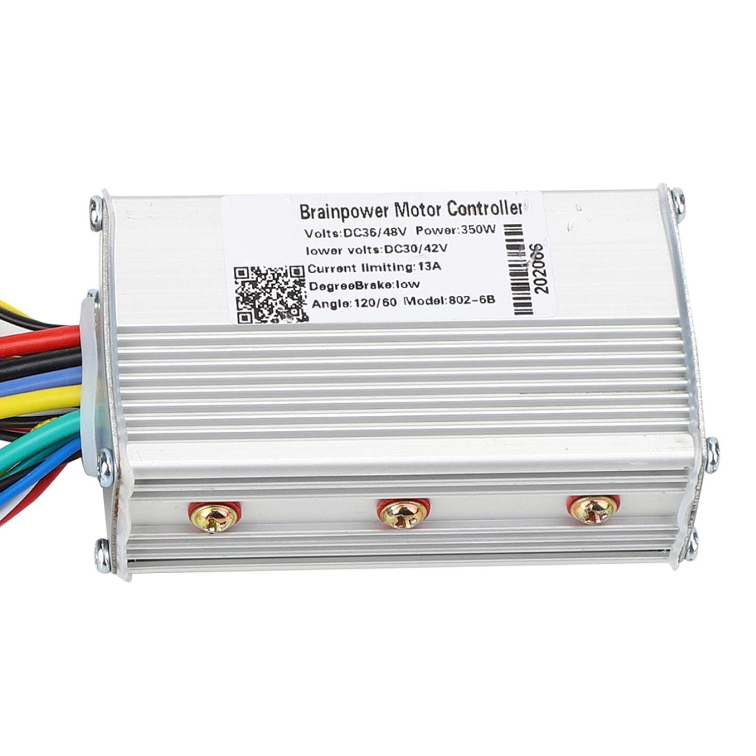
Figure 4.1: Close-up view of the Thincol Motor Brushless Controller unit.

Figure 4.2: The LCD display and half-throttle assembly with key switch.

Figure 4.3: The included throttle grips for handlebar installation.
4.2 Wiring Diagram and Connections
Carefully follow the wiring instructions below. Incorrect wiring can damage the controller or other components. Refer to Figure 4.4 for a visual guide.
- White: Power supply positive
- Yellow: Switch output
- Brown: Signal sending
- Green: Signal reception
- Black: Power supply negative
- Red: +5V (for specific sensors/accessories)
- Blue: Speed control signal
- Black: GND (Ground)
Additional connections include:
- Motor for Hall wire
- Motor three-phase line
- Main switch interface (or electric control lock)
- E-Bike lights horn power supply
- Hall linear EABS brake
- 1:1 power sensor
- LCD instrument interface
- Low brake power off
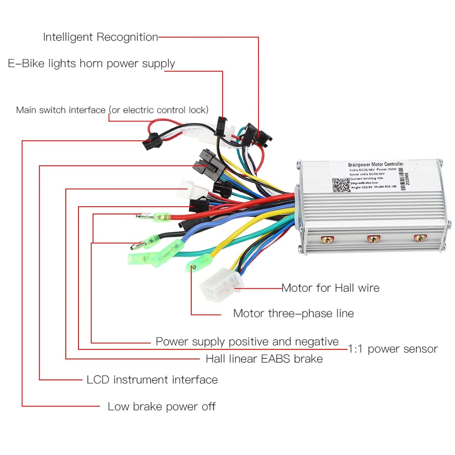
Figure 4.4: Detailed wiring diagram for the Thincol Motor Brushless Controller, showing connections for various components.
Ensure all connections are secure and properly insulated to prevent short circuits or damage.
5. Operating Instructions
5.1 Power On/Off
Insert the key into the ignition switch on the throttle assembly (Figure 4.2) and turn it to the 'ON' position to power on the system. The LCD display will illuminate. Turn the key to 'OFF' to power down.
5.2 Voltage Identification and Display
The controller features universal voltage identification, automatically adapting to 36V or 48V systems. The LCD display provides real-time voltage readings, allowing you to accurately monitor the remaining battery charge.
5.3 Throttle Operation
The included throttle handle acts as the accelerator. Rotate the throttle grip to control the motor speed. The system is designed for smooth and responsive acceleration.
6. Maintenance
To ensure optimal performance and longevity of your Thincol Motor Brushless Controller, follow these maintenance guidelines:
- Keep Clean: Regularly clean the controller unit and display with a dry, soft cloth. Avoid using harsh chemicals or abrasive materials.
- Inspect Connections: Periodically check all wiring connections for tightness and signs of wear or corrosion. Ensure they are secure and properly insulated.
- Protect from Moisture: While the controller is designed for outdoor use, avoid prolonged exposure to heavy rain or submersion in water. Ensure all connectors are dry before operation.
- Avoid Physical Damage: Protect the controller and display from impacts or drops.
7. Troubleshooting
If you encounter issues with your Thincol Motor Brushless Controller, refer to the following common troubleshooting steps:
- System Does Not Power On:
- Ensure the battery is charged and properly connected.
- Verify the key is fully inserted and turned to the 'ON' position.
- Check the main power connections to the controller.
- Motor Does Not Respond to Throttle:
- Confirm the throttle handle is securely connected to the controller.
- Check the motor phase wires and Hall sensor wires for proper connection.
- Ensure the brake levers are not engaged, as some systems have a low brake power-off feature.
- Inaccurate Voltage Reading on LCD:
- Verify the LCD display's connection to the controller.
- Ensure the battery voltage is within the 36V-48V operating range.
If these steps do not resolve the issue, consult a qualified technician or contact customer support.