1. Product Overview
The EpRec 100A Solar Charge Controller is designed to manage power flow from your solar panels to your battery bank and DC loads. It features automatic 12V/24V system voltage recognition, a multi-function LCD display, and dual USB ports for charging devices. This controller utilizes PWM (Pulse Width Modulation) technology with intelligent charging algorithms, often referred to as 'compatible MPPT' for its efficiency in detecting maximum charging current.

Image 1.1: Front view of the EpRec 100A Solar Charge Controller, highlighting the LCD display, control buttons (MENU, PAGE UP, PAGE DOWN), dual USB ports, and connection terminals for solar panels, battery, and load.
2. Safety Instructions
Please read and understand all safety instructions before installation and operation to prevent damage to the controller, battery, or other components.
- Ensure the battery has sufficient voltage for the controller to recognize the battery type before the first installation.
- Keep battery cables as short as possible to minimize power loss.
- The controller is compatible with lead-acid batteries (OPEN, AGM, GEL) and lithium batteries.
- This charge regulator is designed exclusively for regulating solar modules. Do not connect any other charging source to the charge regulator.
- The controller provides reverse polarity protection for both the battery and solar panels.
- It includes thunder protection.
- In case of low battery voltage, the controller will automatically disconnect the load. The load will reconnect when the battery voltage returns to normal.
- The controller automatically compensates charging voltage based on ambient temperature changes.

Image 2.1: Visual representation of the controller's built-in security protections, including short-circuit, overload, overcharge, undervoltage, and overvoltage protection.
3. Product Features
- Intelligent Charging: Features PWM intelligent charging technology to detect maximum charging current, enhancing efficiency.
- Multi-function LCD Display: Provides real-time data including charging and discharging current, cumulative power generation, temperature, and battery voltage.
- Automatic System Voltage: Automatically adapts to 12V or 24V battery systems.
- Dual USB Ports: Two 5V/2A USB outputs for convenient charging of mobile devices.
- Industrial-grade Master Chip: Ensures 16AD sampling accuracy for precise monitoring.
- Comprehensive Protection: Built-in protections against short-circuit, open-circuit, reverse polarity, overload, and over-discharge.
- Adjustable Parameters: Allows adjustment of charge and discharge parameters with power-off memory.
4. Setup and Installation
Follow the connection sequence carefully to avoid damage to the controller.
- Connect the Battery: Connect the battery to the charge controller's battery terminals (positive and negative). Ensure correct polarity.
- Connect the Solar Panels: Connect the photovoltaic module (solar panels) to the charge controller's solar panel terminals (positive and negative). Ensure correct polarity.
- Connect the Load: Connect your DC load (e.g., lights) to the charge controller's load terminals (positive and negative). Ensure correct polarity.
Important: The reverse order applies when disconnecting components. An improper connection sequence can damage the controller.

Image 4.1: Step-by-step connection diagram illustrating the correct order: 1. Connect Battery, 2. Add Solar Panels, 3. Optional Load.
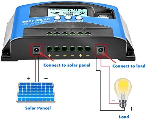
Image 4.2: Detailed wiring diagram showing connections from the solar panel to the controller, and from the controller to a battery and a DC load (light bulb).
5. Operating Instructions
5.1. LCD Display
The LCD displays various system parameters and status indicators:
- Battery Voltage: Shows the current battery voltage.
- Light Delay Timing: Indicates settings for light control.
- Solar Input Indication: Shows if solar panels are connected and providing power.
- Charging Indication: Displays charging status (e.g., charging, floating, full).
- Battery Power Indicator: Graphic representation of battery charge level.
- Load Indication: Shows if the load output is active.
- Current Display: Real-time display of solar panel charge current and load discharge current.
5.2. Button Functions
- MENU Button: Short press to cycle through display interfaces. Long press (3 seconds) to enter or exit parameter setting mode.
- UP Button: Used to increase values when in parameter setting mode.
- DOWN Button: Used to decrease values when in parameter setting mode.
5.3. Parameter Settings
To adjust parameters:
- Long press the MENU button for 3 seconds to enter the setting interface.
- When a number on the interface is flashing, use the UP or DOWN buttons to adjust the value.
- After setting, the system will automatically save the value and exit the setup menu.
5.4. Load Working Modes
The controller supports various load working modes:
- [24H] (Load output 24 hours): The load will be continuously powered, except when the battery voltage is below the low voltage disconnection (LVD) threshold.
- [1-19H] (Load on after sunset and closed after setting hours): The load will turn on automatically after sunset and remain on for the set number of hours (1 to 19).
- [0H] (Dusk to dawn): The load will turn on automatically after sunset and remain on until dawn.
Note on Light Control: The light control function relies on the solar panel. Ensure the solar panel is connected for this function to operate correctly.
6. Maintenance
To ensure optimal performance and longevity of your solar charge controller, consider the following maintenance practices:
- Regularly inspect all wiring connections to ensure they are secure and free from corrosion.
- Keep the controller clean and free from dust and debris. Use a dry cloth for cleaning.
- Ensure adequate ventilation around the controller to prevent overheating.
- Periodically check battery terminals for corrosion and clean if necessary.
7. Troubleshooting
Refer to the table below for common issues and their probable solutions:
| Situation | Probable Cause | Solution |
|---|---|---|
| Charge icon not on when sunny | Solar panel disconnected or open circuit | Reconnect solar panel |
| Load icon off | Incorrect wiring or settings | Verify wiring and load settings |
| Load icon slow flashing | Load overload or short circuit | Reduce load wattage or remove short circuit. Automatic recovery after 5 minutes. |
| Controller powers off | Battery voltage too low or reverse polarity | Check battery voltage and connection polarity |
8. Specifications
| Parameter | Value |
|---|---|
| Model | 100A |
| System Voltage | 12V/24V Auto |
| Max Solar Panel Wattage (12V System) | 1200W |
| Max Solar Panel Wattage (24V System) | 2400W |
| Max Solar Panel Open Circuit Voltage (12V System) | 17V-23V |
| Max Solar Panel Open Circuit Voltage (24V System) | 36V-46V |
| Charge Current | 100A |
| Discharge Current | 100A |
| USB Output | Dual 5V/2A |
| Equalization Voltage | 14.4V (Default, Adjustable) |
| Float Charge Voltage | 13.7V (Default, Adjustable) |
| Discharge Stop Voltage | 10.7V (Default, Adjustable) |
| Discharge Reconnect Voltage | 12.6V (Default, Adjustable) |
| Self-Consume | <10mA |
| Operating Temperature | -35°C to +60°C |
| Product Dimensions | 5 x 3 x 1 inches |
| Item Weight | 11 ounces |
| Display Type | LCD |
9. Warranty and Support
This product comes with a 30-day money-back guarantee and a 12-month warranty for quality-related issues. For any questions or technical assistance, please contact our professional after-sale service team. Our technicians are available to provide support and resolve any issues you may encounter.