OUYZGIA 200000142
OUYZGIA TB6600 Stepper Motor Driver Instruction Manual
Model: 200000142
1. Introduction
This manual provides detailed instructions for the installation, configuration, and operation of the OUYZGIA TB6600 Stepper Motor Driver. This driver is designed for controlling 2-phase and 4-phase hybrid stepper motors, including Nema 17, 23, and 34 series, with a current rating of up to 4.0A. It features optocoupler isolated signal input for strong anti-interference capabilities and supports various subdivision options.

Figure 1: Front view of the OUYZGIA TB6600 Stepper Motor Driver.
2. Specifications
- Input Voltage: 9-42V DC
- Output Current: 0.5A - 4.0A (adjustable)
- Subdivision Options: 1, 2, 4, 8, 16, 32 (1/2/4/8/16/32)
- Compatible Motors: 2-phase and 4-phase hybrid stepper motors (Nema 17, 23, 34)
- Signal Input: Single-ended, pulse/direction, optocoupler isolated (3.3-24V direct connection)
- Protection Features: Overheat, overcurrent, undervoltage lockout, input voltage reversal protection
- Standstill Feature: Current automatically halved at standstill
- Dimensions: Approximately 3.94 x 7.87 x 14.57 inches (100 x 200 x 370 mm)
- Item Weight: 7.4 ounces (0.21 Kilograms)
- Material: Copper

Figure 2: Physical dimensions of the TB6600 Stepper Motor Driver.
3. Setup and Wiring
Proper wiring and configuration are crucial for the correct operation of the stepper motor driver. Ensure all connections are secure before applying power.
3.1. Interface Description
The driver features several input and output interfaces:
- PUL+ / PUL-: Step Pulse signal input.
- DIR+ / DIR-: Motor Direction control Signal input.
- EN+ / EN-: Motor Enable signal input.
- A+ / A-: Connects to motor winding phase A.
- B+ / B-: Connection to motor winding phase B.
- VCC / GND: Power supply input (9-42V DC).
The ENA (Enable) terminal can be left unconnected. When ENA is activated, the motor rotor is free (offline), allowing manual rotation of the motor shaft for adjustment. After adjustment, set ENA to the inactive state for automatic control.

Figure 3: Detailed view of the driver's input/output interfaces and DIP switches.
3.2. Control Signal Wiring
The input signals (Pulse, Direction, Enable) can be connected using either common anode or common cathode methods. The external signal (3.3-24V) can be connected directly without a series resistor.

Figure 4: Common Anode connection diagram. This method uses active low signals.

Figure 5: Common Cathode connection diagram. This method uses active high signals.
3.3. Motor Wiring
The TB6600 driver is compatible with 4, 6, and 8-wire 2-phase/4-phase hybrid stepper motors. Refer to your motor's specifications for correct winding identification. Connect motor windings A and B to the corresponding A+/A- and B+/B- terminals on the driver.

Figure 6: Examples of wiring methods for 4-wire, 6-wire, and 8-wire stepper motors.
3.4. DIP Switch Settings
The TB6600 driver features DIP switches for setting the microstep subdivision and output current. It is recommended to adjust these settings when the power is off.
3.4.1. Microstep Subdivision Setting (SW1-SW3)
Switches SW1, SW2, and SW3 control the microstep resolution. The subdivision determines the number of pulses per revolution for the motor. The stepping motor pitch angle after subdivision is calculated as: Motor inherent step angle / subdivision number.
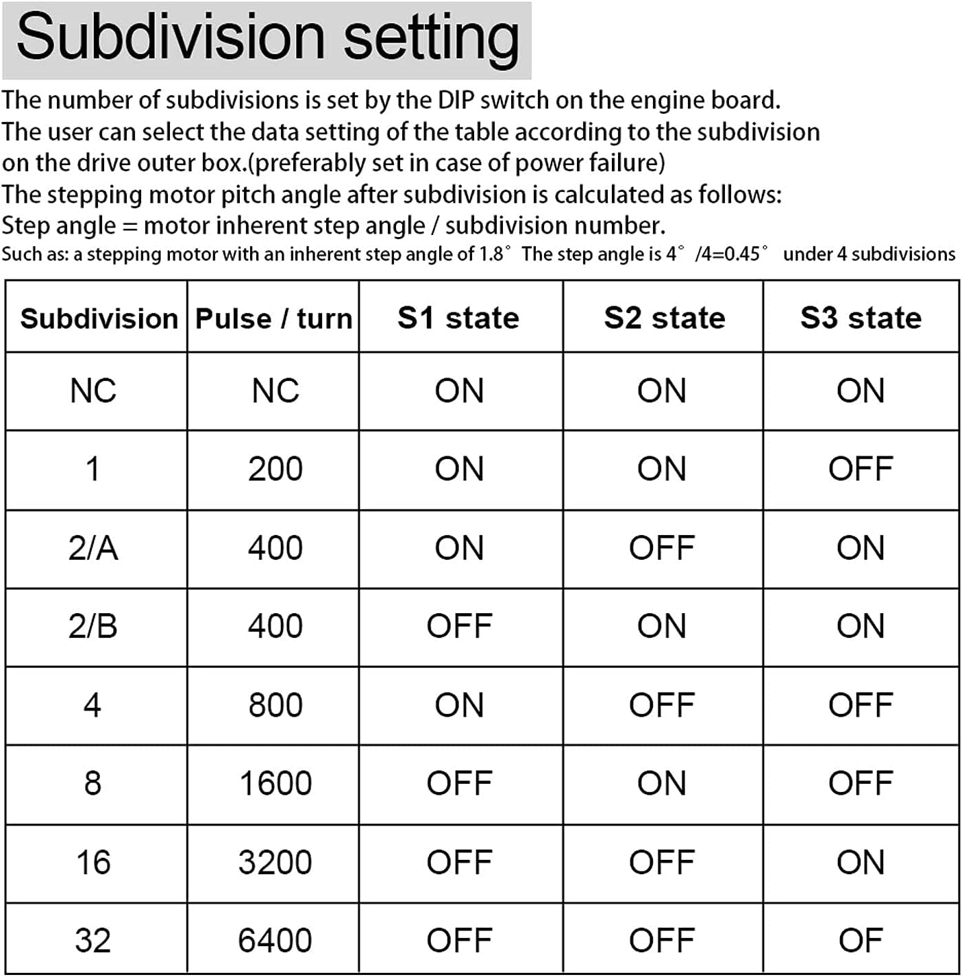
Figure 7: Table for setting microstep subdivision using DIP switches SW1, SW2, and SW3.
| Subdivision | Pulse / Turn | SW1 State | SW2 State | SW3 State |
|---|---|---|---|---|
| NC | NC | ON | ON | ON |
| 1 | 200 | ON | ON | OFF |
| 2/A | 400 | ON | OFF | ON |
| 2/B | 400 | OFF | ON | ON |
| 4 | 800 | ON | OFF | OFF |
| 8 | 1600 | OFF | ON | OFF |
| 16 | 3200 | OFF | OFF | ON |
| 32 | 6400 | OFF | OFF | OFF |
3.4.2. Current Setting (SW4-SW6)
Switches SW4, SW5, and SW6 control the output current to the motor. Set the current according to your stepper motor's rated current to prevent overheating or underperformance.

Figure 8: Table for setting output current using DIP switches SW4, SW5, and SW6.
| Current (A) | SW4 State | SW5 State | SW6 State |
|---|---|---|---|
| 0.5 | ON | ON | ON |
| 1.0 | ON | OFF | ON |
| 1.5 | ON | ON | OFF |
| 2.0 | ON | OFF | OFF |
| 2.5 | OFF | ON | ON |
| 2.8 | OFF | OFF | ON |
| 3.0 | OFF | ON | OFF |
| 3.5 | OFF | OFF | OFF |
| 4.0 | OFF | OFF | OFF |
4. Operating Instructions
Once the driver is correctly wired and configured, it is ready for operation. The driver receives pulse and direction signals from a controller (e.g., microcontroller, CNC board) to move the stepper motor.
- Pulse Signal (PUL): Each pulse received by the driver causes the motor to move one step (or microstep, depending on subdivision settings).
- Direction Signal (DIR): The state of this signal determines the rotation direction of the motor.
- Enable Signal (EN): When active, the motor is energized and holds its position. When inactive, the motor is de-energized and can be freely rotated.
Ensure your control system provides clean, stable pulse and direction signals within the specified voltage range (3.3-24V).
5. Maintenance
The TB6600 stepper motor driver is designed for reliable operation with minimal maintenance. Follow these guidelines to ensure longevity:
- Environmental Conditions: Operate the driver within its specified temperature and humidity ranges. Avoid dusty or corrosive environments.
- Heat Dissipation: Ensure adequate airflow around the driver, especially around the heatsink fins, to prevent overheating. Do not obstruct the heatsink.
- Connections: Periodically check all wiring connections for tightness and signs of wear or corrosion. Loose connections can lead to erratic behavior or damage.
- Cleaning: If necessary, gently clean the driver with a soft, dry cloth. Do not use liquid cleaners or solvents.
6. Troubleshooting
If you encounter issues with your TB6600 stepper motor driver, consider the following troubleshooting steps:
- Motor Not Moving:
- Verify power supply voltage is within 9-42V DC and correctly polarized.
- Check motor wiring for correct phase connections (A+/A-, B+/B-).
- Ensure pulse (PUL) and direction (DIR) signals are being sent from the controller.
- Confirm the Enable (EN) signal is active (motor not in offline state).
- Check DIP switch settings for current and subdivision. Ensure current is sufficient for the motor.
- Erratic Motor Movement or Missed Steps:
- Reduce the pulse frequency from the controller.
- Check for electrical noise on signal lines. Use shielded cables if necessary.
- Ensure motor current is set correctly; too low current can cause missed steps.
- Verify mechanical load on the motor is not excessive.
- Driver Overheating:
- Ensure adequate ventilation and airflow around the heatsink.
- Check if the output current setting (DIP switches SW4-SW6) is too high for the motor.
- Verify the input voltage is not exceeding 42V.
- Motor Vibrates but Does Not Rotate:
- Incorrect motor phase wiring. Double-check A+/A- and B+/B- connections.
- Insufficient current setting.
7. Safety Warnings
Observe the following safety precautions during installation and operation:
- Always disconnect power before making or changing any wiring connections.
- Ensure proper grounding for the power supply and system components.
- Do not exceed the maximum input voltage of 42V DC.
- Avoid touching the driver's heatsink during operation, as it may become hot.
- Protect the driver from moisture, dust, and conductive debris.

Figure 9: General accessory and handling warnings, including precautions against choking, accidental swallowing, moisture, and physical damage.
8. Warranty and Support
For warranty information or technical support, please refer to the product's purchase documentation or contact your retailer. Keep your proof of purchase for any warranty claims.
Related Documents - 200000142
 |
TB6600 Stepper Motor Driver User Guide User guide for the TB6600 Stepper Motor Driver, detailing its features, electrical specifications, wiring, DIP switch settings, and troubleshooting. |
 |
TB6600 Stepper Motor Driver User Guide A comprehensive user guide for the DFRobot TB6600 Stepper Motor Driver, detailing its features, electrical specifications, wiring instructions, DIP switch settings for microstepping and current control, off-line function, FAQs, and dimensions. This driver supports two-phase stepper motors and offers adjustable microstepping and current output for precise motion control. |
 |
TB6600 Stepping Motor Driver Manual: High Performance, Low Cost User manual for the TB6600 stepping motor driver, detailing its high-performance features, low-cost design, electrical specifications, wiring diagrams, microstep and current settings, and operational guidance for 57 and 42 type stepping motors. |
 |
Technical Specifications: 57HS82 Stepper Motor, Drivers, and Power Supply Technical data sheet for 57HS82 Hybrid Stepper Motor, TB6600, DM542, and DM556 drivers, and 350W 24V power supply. Includes electrical and mechanical specifications. |
 |
Stepper Motor Driver Connection and Installation Guide: DM542, DM556, TB6600 A comprehensive technical guide for connecting and installing DM542, DM556, and TB6600 stepper motor drivers. Includes wiring diagrams for common anode and common cathode configurations, along with configuration tables for current and microstepping. |
 |
YOSO Motion Stepper Motors and Drivers: Comprehensive Product Catalog Explore the full range of YOSO Motion stepper motors and drivers, including detailed specifications, series information, and selection guides for various applications. Find NEMA size, electrical specifications, and mechanical dimensions. |
Ask a question about this manual
Ask about setup, troubleshooting, compatibility, parts, safety, or missing instructions. Manuals+ will review the question and use this page’s manual context to help answer it.