Diginex HFeng
Diginex HFeng RFID Access Control System Kit Instruction Manual
Model: HFeng
1. Product Overview
The Diginex HFeng RFID Access Control System Kit provides a secure and convenient solution for managing access to your premises. This kit includes an IP68 waterproof access control keypad, an electric strike lock, a power supply, a door exit button, and RFID keyfobs. It supports multiple identification methods including RFID card, password, or a combination of both.

Image 1.1: Complete Diginex HFeng RFID Access Control System Kit, showing the keypad, exit button, electric strike lock, power supply, and RFID keyfobs.
2. Kit Components
The kit includes the following main components:
- Access Control Keypad: An IP68 waterproof touch screen keypad with a blue backlight, supporting 3000 users. It features a WG26/34 interface and a doorbell button.
- Electric Strike Lock: A stainless steel NC (Fail Safe) type lock, meaning it locks when powered on and unlocks when power is off. Suitable for wooden and metal doors.
- Power Supply: Converts AC100V-260V to DC12V/3A, with an adjustable time delay of 0-15 seconds.
- Door Exit Button: A hard plastic button supporting both NC (Fail Safe) and NO (Fail Secure) modes.
- RFID Keyfobs: 10 pieces of 125KHz EM4100 compatible keyfobs, each pre-programmed with a unique identity number.
2.1 Access Control Keypad

Image 2.1: Close-up of the IP68 waterproof access control keypad, demonstrating its resistance to water.
The keypad is designed for outdoor use, featuring an IP68 waterproof rating. It allows access via RFID card, password, or a combination of both.

Image 2.2: Dimensions of the access control keypad, showing its length, width, and thickness.
2.2 Electric Strike Lock
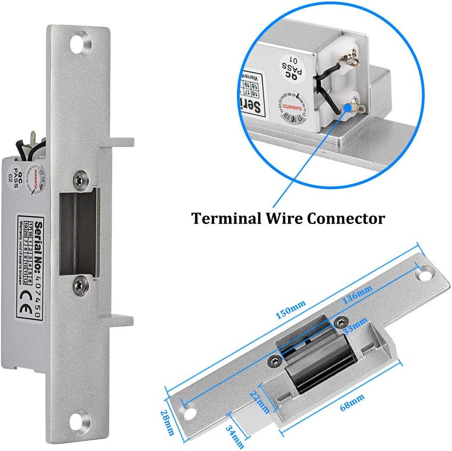
Image 2.3: Detailed view of the electric strike lock, including its dimensions and terminal wire connector.
This NC (Fail Safe) electric strike lock is designed to secure doors. It requires power to remain locked and will unlock if power is interrupted. This is important for emergency egress in certain applications.
2.3 Power Supply Control
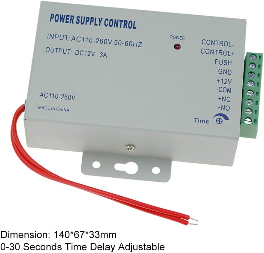
Image 2.4: The power supply control unit, showing input/output specifications and adjustable time delay.
The power supply unit provides stable DC12V power to the system and includes an adjustable time delay for door opening.
2.4 Door Exit Button and RFID Keyfobs

Image 2.5: The door exit button and a set of 10 blue RFID keyfobs.
The exit button allows for convenient egress from the secured area. The RFID keyfobs are used for card-based access.
3. Setup and Installation
Careful installation and wiring are crucial for the proper functioning of the access control system. It is recommended to consult a qualified electrician if you are unsure about any steps.
3.1 Wiring Diagram

Image 3.1: Comprehensive wiring diagram illustrating connections between the access controller, power supply, electric strike lock, and exit button.
Follow the wiring diagram carefully. Ensure all connections are secure and correctly matched to avoid damage to the components or improper operation.
- Connect the Access Controller to the Power Supply according to the diagram.
- Connect the Electric Strike Lock to the Power Supply. Note that this is an NC (Fail Safe) lock.
- Connect the Exit Button to the Access Controller and Power Supply as shown.
- Ensure the AC110-260V input to the Power Supply is correctly connected to your main power source.
3.2 Mounting Components
- Access Control Keypad: Mount the keypad at a convenient height near the door. Use appropriate screws and anchors for your wall type. Ensure the wiring can be routed discreetly and securely.
- Electric Strike Lock: Install the strike lock into the door frame, aligning it with the door's latch bolt. Ensure smooth operation without obstruction.
- Power Supply: Mount the power supply unit in a secure, dry location, preferably near the access control system components.
- Door Exit Button: Install the exit button on the inside of the door, at a comfortable height for users.
4. Operating Instructions
This section details how to program and operate your access control system.
4.1 Initial Setup and Programming Mode
- Enter Programming Mode: Press # then enter the default master password (usually 123456) then press # again. The indicator light will change, confirming entry into programming mode.
- Change Master Password (Recommended): While in programming mode, press 0, enter your new 6-digit master password, then press #. Re-enter the new master password and press # to confirm.
- Exit Programming Mode: Press * to exit programming mode.
4.2 Adding Users (Cards/Passwords)
The system supports up to 3000 users.

Image 4.1: A hand pressing a key on the access control keypad, highlighting the touch interface.
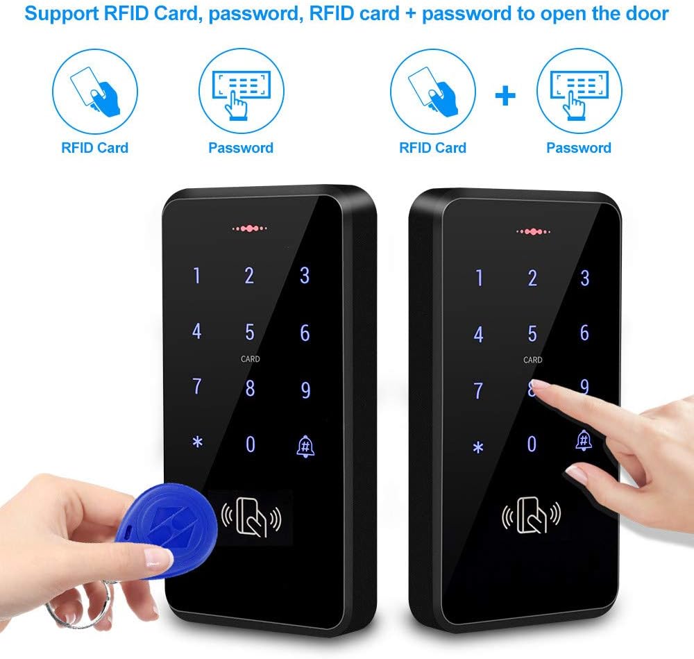
Image 4.2: Illustrations showing the three access methods: RFID card, password, and a combination of RFID card and password.
- Add RFID Card User:
- Enter Programming Mode.
- Press 1.
- Present the RFID card to the keypad. The keypad will beep to confirm.
- To add more cards, present them one by one.
- Press * to exit adding cards, then * again to exit programming mode.
- Add Password User:
- Enter Programming Mode.
- Press 2.
- Enter a 4-6 digit user ID (e.g., 0001) then press #.
- Enter the desired 4-6 digit password, then press #.
- Press * to exit adding passwords, then * again to exit programming mode.
- Add Card + Password User:
- Enter Programming Mode.
- Press 3.
- Present the RFID card to the keypad.
- Enter the desired 4-6 digit password, then press #.
- Press * to exit adding users, then * again to exit programming mode.
4.3 Deleting Users
- Delete RFID Card User:
- Enter Programming Mode.
- Press 4.
- Present the RFID card to be deleted to the keypad. The keypad will beep.
- Press * to exit deleting cards, then * again to exit programming mode.
- Delete Password User:
- Enter Programming Mode.
- Press 5.
- Enter the user ID of the password user to be deleted (e.g., 0001) then press #.
- Press * to exit deleting passwords, then * again to exit programming mode.
4.4 Adjusting Door Opening Time
The power supply allows adjustment of the door opening time (0-15 seconds).
- Locate the 'Time' potentiometer on the power supply unit (refer to Image 2.4).
- Use a small screwdriver to rotate the potentiometer clockwise to increase the delay or counter-clockwise to decrease it.
5. Maintenance
Regular maintenance ensures the longevity and reliable operation of your access control system.
- Cleaning: Wipe the keypad and other components with a soft, damp cloth. Avoid abrasive cleaners or solvents.
- Inspection: Periodically check all wiring connections for signs of wear or damage. Ensure the electric strike lock operates smoothly and is free of debris.
- Power Supply: Ensure the power supply unit is kept in a dry, well-ventilated area.
- Keyfobs: Keep RFID keyfobs away from strong magnetic fields to prevent potential data corruption.
6. Troubleshooting
If you encounter issues with your access control system, refer to the following common problems and solutions:
- Keypad Not Responding:
- Check power connections to the keypad and power supply.
- Ensure the keypad is receiving adequate power (DC12V).
- Door Not Unlocking with Valid Card/Password:
- Verify the user card/password is correctly programmed into the system.
- Check wiring between the keypad, power supply, and electric strike lock. Ensure NC connections are correct for the fail-safe lock.
- Inspect the electric strike lock for any mechanical obstructions.
- Ensure the power supply is providing consistent DC12V to the lock.
- Door Unlocks Automatically (Fail Safe Lock):
- This is expected behavior for an NC (Fail Safe) lock if power is lost. Check for power outages or issues with the power supply.
- Difficulty Programming Cards/Passwords:
- Ensure you are correctly entering and exiting programming mode using the master password.
- Double-check the sequence of key presses for adding/deleting users.
- Verify the master password has not been changed or forgotten. If forgotten, a factory reset might be necessary (consult support).
- Exit Button Not Working:
- Check the wiring connections of the exit button to the access controller and power supply.
- Ensure the exit button is configured for the correct mode (NC/NO) if applicable.
7. Specifications
Detailed technical specifications for the components of the Diginex HFeng RFID Access Control System Kit:
7.1 Access Control Keypad
- User Capacity: 3000
- Material: ABS high quality material
- Panel: Touch screen panel
- Waterproof Level: IP68
- Working Frequency: 125KHz
- Card Reading Type: Support EM compatible card
- Card Reading Distance: 0-10CM
- Identification Method: Card, password, card + password
- Backlight: Blue backlight
- Doorbell Button: Support wired doorbell
- Wiegand Signal: WG26/34 input/output
- Working Voltage: DC 12V
- Working Current: ≤ 30mA
- Door Opening Time: 0-255 seconds (adjustable via keypad programming)
- Working Temperature: -20 °C ~ 70 °C
- Working Humidity: 20% ~ 90%
- Product Size: 140*70*16mm
7.2 Electric Strike Lock
- Material: Stainless steel
- Working Voltage: DC12V +/- 10%
- Working Current: 110mA-250mA
- Performance Testing: 1,000,000 time aging test
- Dimension: 150*28 mm
- Opening Mode: 90 degree swinging door
- Secure Mode: NC type = fail safe type (Locked when power on, unlocked when power off)
- Suitable for: Wooden door, metal door
7.3 Power Supply
- Material: Steel
- AC Input: Standard AC100V-260V / 50-60HZ
- DC Output: DC12V/ 3 A
- Time Delay: 0-15 seconds adjustable
- Dimension: 140X67X33mm (L/W/H)
7.4 Door Exit Button
- Material: Hard Plastic
- Maximum Power Rating: 36V DC 3A—5A output
- Support Modes: NC Mode (Fail Safe Mode) & NO Mode (Fail Secure Mode)
- Dimension: 86X86MM
7.5 RFID Keyfobs
- Material: ABS
- Operating Frequency: 125kHz
- Detection Range: 0-10cm
- Quantity: 10 pieces
- Feature: Each card pre-programmed with a unique identity number
8. Warranty and Support
For warranty information and technical support, please contact your retailer or the manufacturer, Diginex. Keep your purchase receipt as proof of purchase.
Ask a question about this manual
Ask about setup, troubleshooting, compatibility, parts, safety, or missing instructions. Manuals+ will review the question and use this page’s manual context to help answer it.