HFBTE Digital Force Gauge 50N
HFBTE Digital Force Gauge 50N Dynamometer User Manual
Model: Digital Force Gauge 50N
Introduction
The HFBTE Digital Force Gauge 50N Dynamometer is a small, simple, multi-functional, and high-precision instrument designed for accurate force measurement. It is widely used across various industries including electronic appliances, construction hardware, light industrial textiles, auto parts, lighters and other ignition devices, fire equipment, pen manufacturing, push-pull load testing, insertion force testing, destructive testing of locks, fishing gear, chemical industry, power machinery, and scientific research institutions.
This digital display instrument offers high resolution, fast sampling speed, and ease of use, making it a new generation of high-efficiency and high-precision push-pull test equipment.
Product Features
- High precision and high resolution for accurate measurements.
- Three measurement modes for selection: Real-time, Peak, and First Peak.
- Supports four units for selection and conversion: N (Newton), Kg (Kilogram), Lb (Pound), and Oz (Ounce).
- Gravity acceleration setting function: Users can input the accurate value of gravity acceleration at the usage location for more precise testing and unit conversion.
- Upper and lower limits can be set for statistical analysis. An audible buzzer alarm will activate if limits are exceeded.
- Minimum force value shielding function: Data within a set minimum range can be ignored.
- Automatic shutdown function: The automatic shutdown time can be set to conserve battery when not in use for a long period.
- Automatic backlight and buzzer alarm functions for enhanced usability.
Package Contents
Upon opening the package, please verify that all components are present and in good condition.

The package includes the main digital force gauge unit, a set of interchangeable tips (flat, conical, chisel, notched, small hook), an extension rod, and a user manual. All items are neatly organized within a protective carrying case.
This image shows the main force gauge unit along with the five different tips: Flat Tip, Conical Tip, Chisel Tip, Notched Tip, and Small Hook. An extension rod is also visible, designed to be screwed into the top of the gauge for extended reach.
Setup
1. Battery Installation
The Digital Force Gauge requires two AAA 1.5V batteries (not included). Follow these steps to install them:
- Locate the battery compartment on the back of the device.
- Slide the battery compartment cover downwards to open it.
- Insert two AAA batteries, ensuring correct polarity (+/-) as indicated inside the compartment.
- Replace the battery compartment cover by sliding it back into place until it clicks securely.
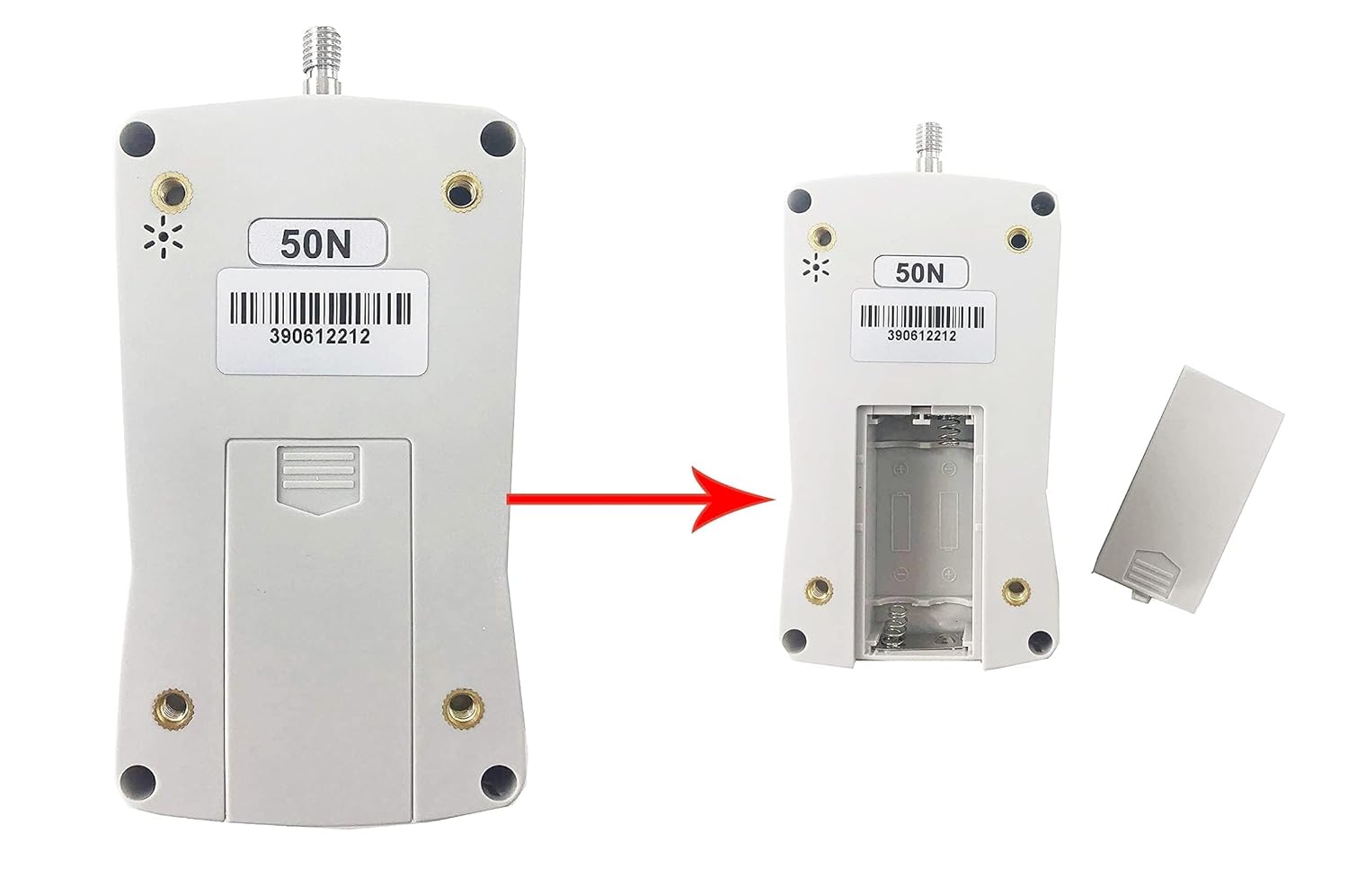
This image demonstrates how to open the battery compartment on the back of the force gauge and insert the AAA batteries. Ensure the correct orientation of the batteries for proper function.
2. Attaching Tips and Extension Rod
Select the appropriate tip for your measurement application. The tips and extension rod can be screwed into the sensor shaft at the top of the force gauge.
- To attach a tip, gently screw it clockwise onto the threaded shaft until secure.
- If extended reach is required, first screw the extension rod onto the sensor shaft, then attach the desired tip to the end of the extension rod.
Operating Instructions
1. Power On/Off
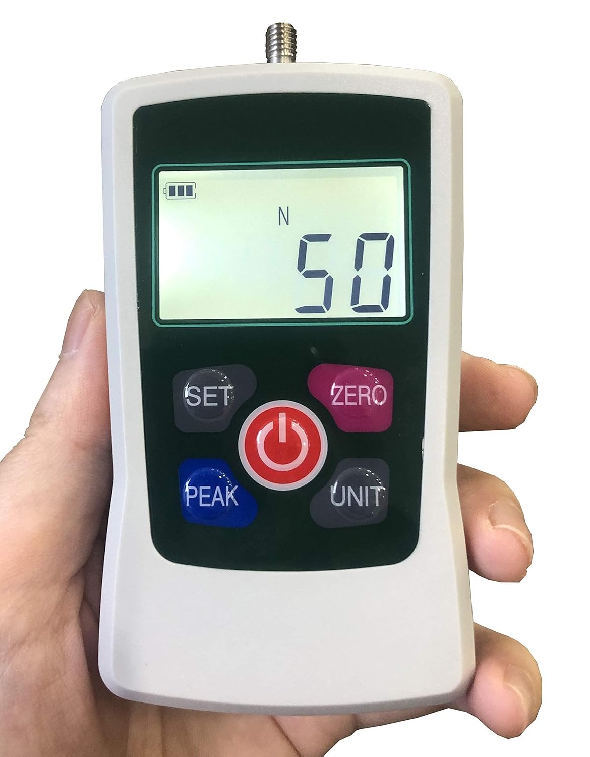
Press the Power button (red circle with power symbol) to turn the device on or off.

This image displays the main interface of the force gauge, highlighting the 'SET', 'ZERO', 'PEAK', 'UNIT', and Power buttons. The digital display shows the current measurement and battery level.
2. Unit Selection
Press the UNIT button to cycle through the available measurement units: Newtons (N), Kilograms (Kg), Pounds (Lb), and Ounces (Oz).
3. Zeroing the Display
Before taking a measurement, ensure the display reads 0.00. If not, press the ZERO button to reset the reading.
4. Measurement Modes
The device supports three measurement modes:
- Real-time Mode: Displays the current force being applied. This is the default mode.
- Peak Mode: Press the PEAK button to enter Peak mode. The display will hold the maximum force value detected during the measurement. Press PEAK again to return to real-time mode.
- First Peak Mode: (Refer to the detailed user manual for specific instructions on activating and using First Peak mode, typically accessed via the SET button or a combination of buttons). This mode captures the first significant peak in force.
5. Setting Parameters (SET Button)
The SET button is used to access advanced settings such as gravity acceleration compensation, upper/lower limits for alarm, and minimum force value shielding. Consult the comprehensive PDF user manual for detailed instructions on configuring these parameters.
For a visual demonstration of basic operation and unit switching, please refer to the video below:
Video: Demonstration of the Digital Force Gauge in operation, showing unit switching and basic measurements. This video is provided by the seller, HFBTE-US.
Maintenance
- Cleaning: Wipe the device with a soft, dry cloth. Do not use abrasive cleaners or solvents.
- Storage: Store the force gauge in its protective case in a dry environment, away from direct sunlight and extreme temperatures.
- Battery Replacement: Replace batteries promptly when the low battery indicator appears on the display to ensure accurate readings and prevent corrosion. Remove batteries if the device will not be used for an extended period.
- Calibration: For professional applications requiring certified accuracy, periodic calibration by a qualified service provider is recommended.
Troubleshooting
| Problem | Possible Cause | Solution |
|---|---|---|
| Device does not power on. | Dead or incorrectly installed batteries. | Check battery polarity. Replace with new AAA batteries. |
| Inaccurate readings. | Device not zeroed; incorrect unit selected; environmental factors (temperature, vibration); need for calibration. | Press ZERO button. Verify correct unit. Ensure stable testing environment. Consider professional calibration. |
| Buzzer alarm sounds continuously. | Measurement exceeds set upper or lower limits. | Reduce applied force or adjust limit settings via the SET button. |
| Display is dim or flickering. | Low battery. | Replace batteries. |
Technical Specifications
| Specification | Value |
|---|---|
| Maximum Load Value | 50N (5kg, 11Lb, 180Oz) |
| Load Division Value | 0.01N; 0.001kg; 0.001Lb; 0.1Oz |
| Sensor Structure | Inner sensor |
| Accuracy | ±1% |
| Power Source | 2 AAA batteries 1.5V (Not Included) |
| Working Temperature | 5°C ∼ 35°C |
| Transport Temperature | -10°C ∼ 60°C |
| Relative Humidity | 15% ∼ 80% RH |
| Working Conditions | No vibration source around and no corrosive environment. |
| Dimensions (L*W*H) | 124 x 60 x 31 mm (4.88 x 2.36 x 1.22 inches) |
| Net Weight | 0.4 KG (14.11 ounces) |
| Material | Plastic |
Warranty and Support
For warranty information, technical support, or service inquiries, please contact HFBTE-US directly through their official Amazon store page or the contact details provided with your purchase. Keep your purchase receipt as proof of purchase for warranty claims.
You can visit the official HFBTE Store on Amazon for more information: HFBTE Store
Ask a question about this manual
Ask about setup, troubleshooting, compatibility, parts, safety, or missing instructions. Manuals+ will review the question and use this page’s manual context to help answer it.