Introduction
This manual provides detailed instructions for the installation, operation, and maintenance of your Mangood 433MHz 12V DC 6 Channel Wireless Remote Control Relay Switch. This device is designed to provide wireless control for various electrical appliances, motors, lights, doors, and windows, offering flexibility and convenience in home, farm, and industrial applications.

Image: The Mangood 433MHz 12V DC 6 Channel Wireless Remote Control Relay Switch module with two accompanying remote controls.
Product Features
- Signal Stability: Utilizes wireless technology for a stable signal. The signal can pass through walls, floors, and doors, allowing for reliable control within a specified range.
- Multiple Work Modes: Supports Self-lock, Momentary, and Inter-lock operating modes, which can be configured by the user.
- Voltage and Load Capacity: Operates with a DC 12V control voltage. The wireless relay can handle a load of 10A at 1V-250V (DC/AC), including 10A 250V AC, 10A 125V AC, 10A 30V DC, 10A 28V DC, and 10A 12V.
- Easy Installation: Designed for straightforward installation without complex wiring, connecting between the power source and the electrical appliance.
- Secure Learning Code: Features a learning function to pair remote controls. Control codes can be deleted and re-learned for security or to add new remotes.
- Wide Application: Suitable for controlling various devices such as LED lamps, lights, wireless monitoring equipment, power switches, small motors, buzzers, electromagnets, laser lights, electronic power supply equipment, TVs, cameras, video signals, audio signals, and electrically operated doors, locks, or windows.
Specifications
| Specification | Value |
|---|---|
| Brand Name | Mangood |
| Model Number | 30029656884 |
| Coil Voltage | 12 Volts DC |
| Current Rating | 10 Amps |
| Maximum Switching Current | 10 Amps |
| Minimum Switching Voltage | 12 Volts (DC) |
| Wattage | 120 watts |
| Operation Mode | Automatic |
| Mounting Type | Surface Mount |
| Number of Terminals | 3 |
| Contact Type | Normally Open |
| Contact Material | Copper Alloy |
| Connector Type | Solder |
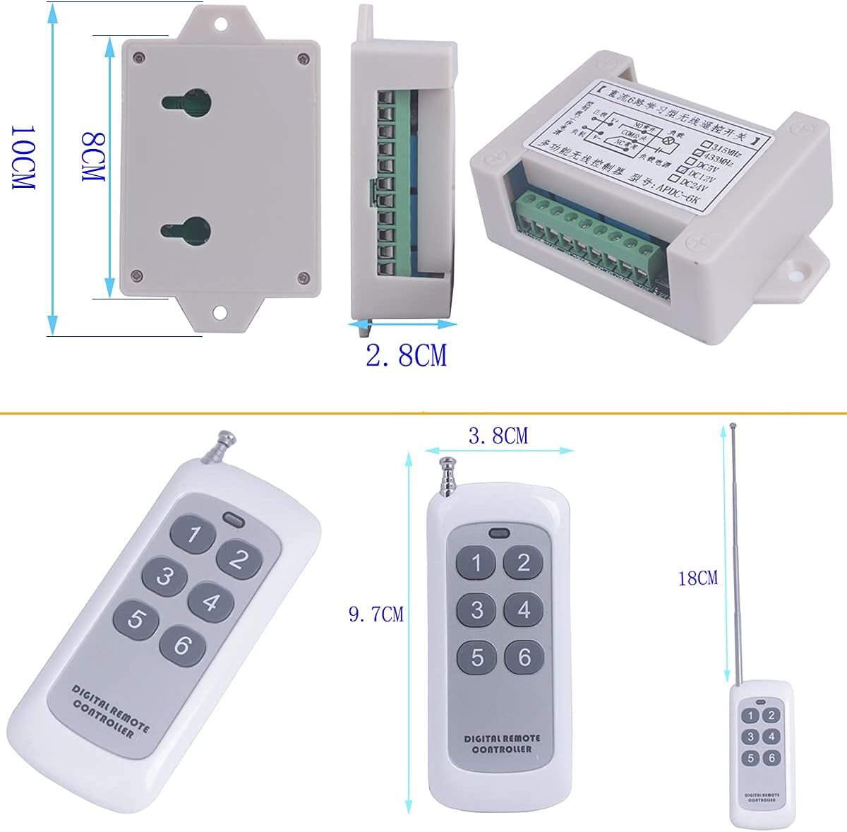
Image: Detailed dimensions of the relay module and the remote control unit.
Setup and Installation
Proper wiring is crucial for the safe and correct operation of the relay switch. Always ensure power is disconnected before performing any wiring. The relay module requires a 12V DC power supply for its operation.
Wiring Diagrams
Refer to the following diagrams for common wiring configurations:

Image: Wiring diagram for controlling 12V loads directly with the relay module.

Image: Wiring diagram for controlling 1V-250V loads using the 12V relay module.

Image: Wiring diagram for controlling 1V-250V motors with forward/reverse functionality using the 12V relay module.
Learning and Clearing Control Codes
The relay module needs to learn the remote control's code to function. You can also clear existing codes or change the working mode.
Video: This video demonstrates how to program the remote control to the relay module and how to clear existing control codes.
Learn Method (Program Remote Control):
- Press and hold the 'Learn Button' on the relay module for 1-2 seconds until the LED lights up.
- While the LED is lit, press any key (e.g., Key NO. 1) on your remote controller 1-3 times. The LED will flash to confirm successful learning.
Clear Control Code:
To clear all learned remote control codes from the module:
- Connect power to the module.
- Press and hold the 'Learn Button' for 8-10 seconds until the LED light turns off. This indicates that all stored control codes have been cleared.
Note: To change the working mode, you must first clear the current control code.

Image: The relay module highlighting the 'Learn Button' and 'Antenna', with text overlays explaining the learn method, clear control code, and work mode choices.
Operating Modes
The relay module supports three primary working modes, which determine how the relay responds to remote control presses. These modes are set during the learning process by pressing a specific button on the remote after the learn button is activated.
Mode Selection:
After pressing the 'Learn Button' on the module (LED lights up), press the corresponding remote control key to select the desired mode:
- Momentary Mode: Press Remote Control Key NO. 1. The relay activates only while the button is pressed and held. It deactivates upon release.
- Self-lock Mode (Toggle): Press Remote Control Key NO. 2. The relay activates with one press and stays active. A second press deactivates it.
- Inter-lock Mode: Press Remote Control Key NO. 3. When one relay activates, all other relays on the module deactivate. This is useful for applications where only one output should be active at a time.
Additional complex modes are available by pressing other keys (4, 5, 6) on the remote during the learning process, combining momentary, self-lock, and inter-lock behaviors across different relays (e.g., Relays 1-3 Momentary, Relays 4-6 Self-lock).
Applications
The Mangood 6-channel wireless remote control relay switch is versatile and can be integrated into various systems for remote operation:
- Home Automation: Control lighting, fans, and other appliances.
- Garage Doors & Gates: Open and close garage doors or automated gates.
- Industrial Control: Operate small motors, pumps, or other machinery.
- Security Systems: Integrate with alarms or monitoring equipment.
- Agricultural Use: Control irrigation systems or farm equipment.

Image: A collage illustrating diverse applications for the wireless relay switch, such as controlling security cameras, stage lights, industrial fans, motors, aquarium equipment, garage doors, electrical cabinets, and agricultural irrigation systems.

Image: A visual representation of the wireless signal's ability to penetrate walls, demonstrating the remote control's range and effectiveness in a typical residential setting.
Troubleshooting
If you encounter issues with your relay switch, consider the following common problems and solutions:
- Remote Control Not Responding:
- Ensure the remote control is paired correctly. Try clearing all codes and re-learning the remote.
- Check the remote control battery.
- Verify that the relay module is receiving power (LED indicator should be on during learning).
- Relay Not Activating/Deactivating Correctly:
- Confirm the correct working mode (Momentary, Self-lock, Inter-lock) is set. If unsure, clear codes and re-learn the remote in the desired mode.
- Inspect all wiring connections for looseness or incorrect placement.
- Ensure the load connected to the relay does not exceed the specified current or voltage ratings (10A, 1V-250V).
- Unexpected Relay Behavior (e.g., multiple relays activating):
- This may indicate an incorrect working mode. Clear all codes and re-program the remote to the desired mode. For example, if only one output should be active at a time, ensure Inter-lock mode is selected.
- Relay Module Not Supplying Power to Device:
- The relay module acts as a switch, not a power supply. It connects or disconnects the power source to your appliance. Ensure your appliance has its own power source or that the relay is correctly wired to switch the main power line to the appliance. The module's output terminals switch the connected load, they do not provide the 12V DC input power directly to the load.
Warranty and Support
Mangood products are manufactured to high-quality standards. For any technical assistance or support, please refer to the seller's contact information or the official Mangood store on Amazon. Keep your purchase receipt for any warranty claims.