1. Introduction
This manual provides detailed instructions for the installation, operation, and maintenance of your Kicker 48KXMA5004 KXMA500.4 4-Channel Full-Range Class-D Marine Amplifier. Please read this manual thoroughly before attempting installation or operation to ensure proper function and safety.
The Kicker KXMA500.4 amplifier is designed for marine environments, featuring conformal-coated circuit boards and 316L stainless-steel hardware to resist moisture and corrosion. It offers a compact design, built-in variable crossovers, and is suitable for powering a variety of marine audio systems.
2. Safety Instructions
- Always disconnect the vehicle's battery before installing or servicing any electrical components.
- Ensure all wiring is properly routed and secured to prevent damage from moving parts or sharp edges.
- Use appropriate gauge wiring for power, ground, and speaker connections as specified in the installation section.
- Protect all power and ground connections with fuses or circuit breakers as close to the battery as possible.
- Avoid mounting the amplifier in areas exposed to direct sunlight, excessive heat, or standing water.
- Consult a professional installer if you are unsure about any part of the installation process.
3. Installation
3.1 Mounting
Select a mounting location that provides adequate ventilation for the amplifier. Ensure the surface is solid and can support the amplifier's weight. Avoid mounting near heat sources or in enclosed spaces without airflow. The amplifier can be mounted on boards or directly to boat surfaces.
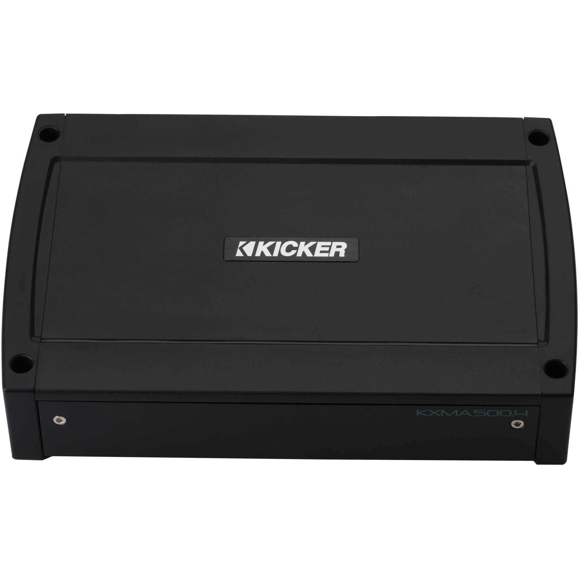
Figure 1: Top view of the Kicker 48KXMA5004 Marine Amplifier, showing its compact design.
3.2 Wiring Connections
Refer to the diagram below for proper wiring connections. Ensure all connections are secure and insulated to prevent short circuits.
- Power (BATT +12V): Connect directly to the positive terminal of the battery using a fuse or circuit breaker within 18 inches of the battery.
- Ground (GND): Connect to a clean, solid metal point on the boat's chassis or a dedicated ground bus. Ensure the connection is free of paint or corrosion.
- Remote (REM): Connect to the remote turn-on lead from your head unit or a switched 12V source.
- Input (AMP1, AMP2): Connect RCA cables from your head unit's pre-amp outputs to the amplifier's input jacks.
- Speaker Output (AMP1 Bridged, AMP2 Bridged): Connect your speakers to the appropriate terminals. Observe correct polarity (+ to + and - to -). For bridged operation, refer to the specific bridging instructions in your head unit's manual.

Figure 2: Rear panel connections of the Kicker 48KXMA5004, showing power, ground, remote, RCA inputs, and speaker outputs.
4. Operation and Settings
The Kicker KXMA500.4 amplifier features adjustable controls for optimal sound tuning.

Figure 3: Front panel controls of the Kicker 48KXMA5004, including gain, crossover, and EQ settings.
4.1 Gain Adjustment
The GAIN control matches the amplifier's input sensitivity to the output level of your head unit. Start with the gain set to minimum. Increase the head unit volume to about 75% of maximum. Slowly increase the amplifier's gain until you hear slight distortion, then back off slightly. The GAIN MATCH indicator will assist in setting the optimal gain.
4.2 Crossover Settings
The amplifier features variable crossovers for each channel pair (AMP1 and AMP2). Use these to direct specific frequency ranges to your speakers.
- OFF/HP/LP/BP Switch: Select the desired crossover mode.
- HI-PASS (HPF): Allows frequencies above the set point to pass. Useful for full-range speakers to prevent low-frequency distortion.
- LO-PASS (LPF): Allows frequencies below the set point to pass. Typically used for subwoofers.
- BAND-PASS (BP): Allows a specific range of frequencies to pass, defined by both HPF and LPF settings.
4.3 KICK EQ
The KICK EQ control provides a bass boost at 40Hz, adjustable from 0 to +12dB. Use this feature to enhance low-frequency response as desired, but avoid excessive boost which can lead to distortion or speaker damage.

Figure 4: Detailed view of the amplifier's control panel, highlighting the gain, crossover, and KICK EQ adjustments.
5. Maintenance
Regular maintenance ensures the longevity and optimal performance of your marine amplifier.
- Cleaning: Periodically wipe the amplifier's exterior with a soft, damp cloth. Avoid using harsh chemicals or abrasive cleaners.
- Connection Inspection: Annually inspect all power, ground, remote, and speaker connections for corrosion or looseness. Clean and tighten as necessary.
- Ventilation: Ensure the amplifier's cooling fins are free from obstructions to allow proper heat dissipation.
- Environmental Protection: While designed for marine use, minimizing direct exposure to saltwater spray and extreme temperatures will extend the amplifier's life.
6. Troubleshooting
If your amplifier is not functioning correctly, refer to the following common issues and solutions before contacting customer support.
| Problem | Possible Cause | Solution |
|---|---|---|
| No Power / Amplifier does not turn on | Blown fuse/circuit breaker; Loose power/ground/remote wire; Faulty remote turn-on signal | Check and replace fuse; Verify all power, ground, and remote connections are secure; Test remote wire for 12V when head unit is on. |
| No Sound Output | No input signal; Speaker wires disconnected/shorted; Amplifier in protect mode; Incorrect gain/crossover settings | Check RCA input cables; Inspect speaker wiring for shorts or disconnections; Check amplifier status indicator; Review gain and crossover settings. |
| Distorted Sound | Gain set too high; Incorrect crossover settings; Damaged speakers; Low voltage | Reduce gain setting; Adjust crossover frequencies; Inspect speakers for damage; Check battery voltage and charging system. |
| Amplifier Overheating | Inadequate ventilation; Low impedance load; Prolonged high volume operation | Ensure proper airflow around amplifier; Verify speaker impedance matches amplifier's capabilities; Reduce volume or allow amplifier to cool. |
7. Specifications
Key technical specifications for the Kicker 48KXMA5004 Marine Amplifier:
| Feature | Detail |
|---|---|
| Model | 48KXMA5004 |
| Brand | KICKER |
| Number of Channels | 4 |
| Output Power | 500 Watts (Total) |
| Mounting Type | Boards, Boat Mount |
| Item Dimensions (L x W x H) | 12 x 21 x 7 inches |
| Item Weight | 6 Pounds |
| UPC | 713034020622 |
| Specification Met | ABYC/NMMA |
8. Warranty Information
This Kicker 48KXMA5004 Marine Amplifier is covered by a 1-Year Manufacturer Warranty. This warranty covers defects in materials and workmanship under normal use. For specific terms, conditions, and claim procedures, please refer to the official Kicker warranty documentation or contact Kicker customer support.
9. Customer Support
For further assistance, technical support, or warranty inquiries, please contact Kicker customer support:
- Website: www.kicker.com
- Phone: Refer to the Kicker website for regional contact numbers.
- Email: Refer to the Kicker website for support email addresses.
Please have your product model number (48KXMA5004) and purchase information ready when contacting support.


