Mangood 2-Channel Motor Remote Control Switch 433MHz
Mangood 2-Channel AC 85V-250V Motor Forward/Reverse Wireless Remote Control Switch Manual
Model: 2-Channel Motor Remote Control Switch 433MHz
Brand: Mangood
1. Introduction
This manual provides detailed instructions for the installation, operation, and maintenance of your Mangood 2-Channel AC 85V-250V Motor Forward/Reverse Wireless Remote Control Switch. This device is designed to provide convenient wireless control for various motors, enabling both forward and reverse motion, and is suitable for a wide range of applications.

Figure 1: Mangood 2-Channel Wireless Remote Control Switch Receiver and two remote key fobs.
2. Product Features
- 2-Channel Wireless Control: The system allows one or multiple transmitters to control one or multiple receivers simultaneously without interference.
- Adjustable Output Modes: Supports Momentary, Self-lock, and Inter-lock output states, adjustable via jumpers on the receiver.
- Pre-configured for Ease of Use: The transmitter and receiver are pre-paired and tested before shipment, requiring no initial setup upon receipt.
- Direct Motor Control: Specifically designed for direct control of motor forward and reverse operations.
- Wide Voltage Range: Operates with AC 85V to 250V input, with output voltage matching the input.
- Integrated Ports: Features dedicated wiring ports for limit switches and manual control buttons.
- Secure Learning Code: Utilizes a learning code control system for enhanced security, allowing easy addition and removal of control codes.
- Broad Application: Ideal for remote control of water pump switches, various motors, electric curtain machines, industrial equipment, sockets, lifting equipment, wireless lamps, windows, entrance gates, and garage doors.

Figure 2: Diverse applications of the Mangood wireless remote control switch.
3. Setup and Installation
3.1 Wiring Instructions
Refer to the wiring diagram below for proper connection of the receiver unit. Ensure all power is disconnected before performing any wiring.

Figure 3: 85V-250V Motor Wiring Diagram.
- Power Input: Connect your AC 85V-250V power supply to the designated '+' and '-' terminals.
- Motor Connection: Connect the motor to the 'Forward', 'COM' (Common), and 'Reverse' terminals. 'COM' is the common terminal for the motor.
- Limit Switches: Connect 'Up Limit' and 'Lower Limit' switches to their respective 'SQ' terminals. These are typically normally closed (NC) switches that open when the limit is reached.
- Manual Control Buttons: Optional manual 'UP', 'STOP', and 'DOWN' push buttons can be connected to their corresponding terminals for local control.
3.2 Work Mode Configuration
The receiver supports three work modes: Momentary, Self-lock, and Inter-lock. These modes are configured using jumpers on the receiver board. Refer to Figure 4 for jumper locations.

Figure 4: Receiver Board Components and Work Mode Settings.
- Momentary Mode: (T S L not Connect) - Output is active only while the remote button is pressed. Release the button, and the output turns off.
- Self-lock Mode: (T S Pin Connect) - Press the remote button once to activate the output; press the same button again to deactivate it.
- Inter-lock Mode: (L S Pin Connect) - Press one remote button to activate its corresponding output and deactivate all other outputs. This mode is typically used for motor forward/reverse control, where pressing 'Forward' deactivates 'Reverse' and vice-versa.
3.3 Learning and Removing Control Codes
The receiver and transmitter are pre-paired. If you need to add new remotes or clear existing codes, follow these steps:
- To Learn a Code:
- Press the learning button on the receiver 1 time for Momentary mode.
- Press the learning button on the receiver 2 times for Self-lock mode.
- Press the learning button on the receiver 3 times for Inter-lock mode.
- After pressing the learning button, the LED indicator on the receiver will light up. Then, press the desired button on your remote control. The LED will flash and turn off, indicating successful pairing.
- To Remove All Codes: Press and hold the learning button on the receiver for 8-10 seconds. The LED indicator will turn off, signifying that all stored codes have been cleared.
4. Operating Instructions
Once the receiver is wired and the work mode is configured, you can operate the connected motor using the remote control.
- Momentary Mode: Press and hold the remote button to activate the motor. Release the button to stop the motor.
- Self-lock Mode: Press the remote button once to start the motor. Press the same button again to stop the motor.
- Inter-lock Mode (for Forward/Reverse): Press the 'Forward' button on the remote to start the motor in the forward direction. Press the 'Reverse' button to stop the forward motion and start the motor in the reverse direction. Pressing a third 'Stop' button (if configured) or the opposite direction button will stop the motor.
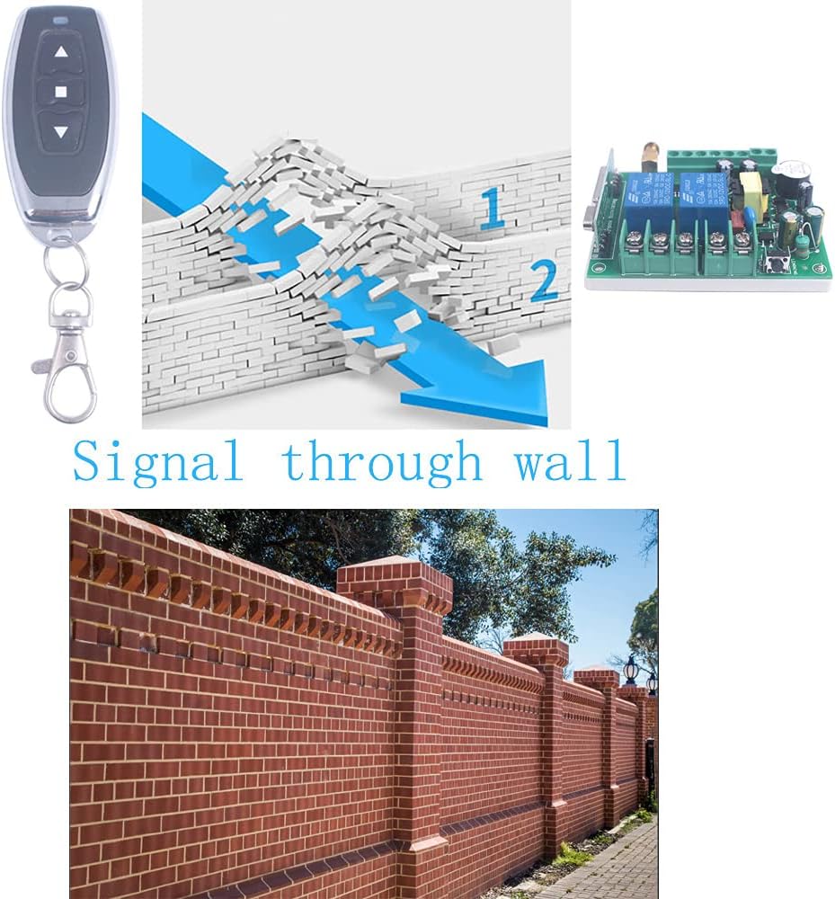
Figure 5: Wireless signal transmission through obstacles.
5. Maintenance
The Mangood wireless remote control switch is designed for reliable operation with minimal maintenance. Follow these general guidelines:
- Cleaning: Keep the receiver unit and remote controls clean and free from dust and debris. Use a dry, soft cloth for cleaning.
- Connections: Periodically check all wired connections to ensure they are secure and free from corrosion.
- Remote Battery: Replace the LR44 batteries in the remote control when the operating range decreases or the remote becomes unresponsive.
- Environment: Ensure the receiver is installed in a location protected from extreme temperatures, moisture, and direct sunlight. The IP65 rating indicates protection against dust and low-pressure water jets, but it is not fully submersible.
6. Troubleshooting
If you encounter issues with your Mangood wireless remote control switch, refer to the following troubleshooting steps:
- Remote Not Responding:
- Check the battery in the remote control and replace if necessary.
- Ensure the remote is within the effective operating range and there are no significant obstructions.
- Re-pair the remote control with the receiver following the 'Learning a Code' instructions in Section 3.3.
- Motor Not Operating or Only Moving One Way:
- Verify that the power supply to the receiver is correct (AC 85V-250V) and stable.
- Check all motor wiring connections (Forward, COM, Reverse) as per Figure 3. Ensure they are secure.
- Confirm that the correct work mode is selected via the jumpers. For forward/reverse motor control, Inter-lock Mode (L+S Pin Connect) is typically required. If only one direction works, the mode might be incorrectly set or the wiring for the other direction is faulty.
- Test the motor directly to ensure it is functional.
- Check if any limit switches are activated, preventing motor movement in a specific direction.
- Intermittent Operation or Reduced Range:
- Ensure the receiver's antenna is properly connected and positioned for optimal signal reception.
- Minimize sources of radio frequency (RF) interference near the receiver or remote.
- Obstacles like thick walls or metal structures can reduce range (refer to Figure 5). Try repositioning the receiver or operating closer to it.
7. Specifications
| Specification | Value |
|---|---|
| Brand | Mangood |
| Operation Mode | Automatic |
| Current Rating | 10 Amps |
| Operating Voltage | 85V - 250V AC |
| Contact Type | Normally Open |
| Connector Type | Wireless |
| Terminal Type | Blade Or Solder |
| Circuit Type | 2-way |
| Actuator Type | Push Button |
| Contact Material | Copper Or Gold |
| International Protection Rating | IP65 |
| Number of Positions | 2 |
| Control Method | Remote |
| Connectivity Protocol | 433MHz RF (Wireless) |
| Wattage | 2500 Watts (Max) |
| Item Weight | 5.3 ounces |
| Package Dimensions | 4.72 x 2.8 x 1.42 inches |
| Remote Batteries | 2 x LR44 batteries (included) |

Figure 6: Receiver and Remote Control Dimensions.
8. Warranty and Support
For warranty information and technical support, please refer to the product packaging or contact the seller directly. Mangood is committed to providing good after-sales service and resolving customer issues.
You can also visit the official Mangood store for more information: Mangood Store
Ask a question about this manual
Ask about setup, troubleshooting, compatibility, parts, safety, or missing instructions. Manuals+ will review the question and use this page’s manual context to help answer it.