1. Introduction
This manual provides essential information for the proper installation, operation, and maintenance of the U/K NTA-5A-2DD Automatic Voltage Regulator (AVR). This AVR is designed for use with specific Denyo and MQ Power Generators to maintain a stable output voltage. Please read this manual thoroughly before attempting any installation or operation.
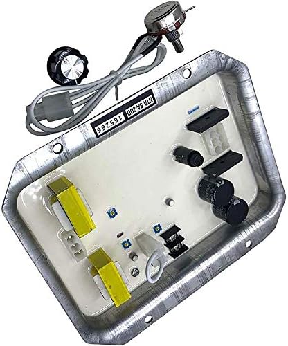
Figure 1: The U/K NTA-5A-2DD Automatic Voltage Regulator module. This image displays the main circuit board with various electronic components, including capacitors and transformers, housed within a metal casing. A separate potentiometer with a control knob is connected via wires, indicating its role in voltage adjustment.
2. Safety Information
Always observe the following safety precautions to prevent injury or damage to equipment:
- Ensure the generator is completely shut down and disconnected from any power source before installing or servicing the AVR.
- Only qualified personnel should perform installation and maintenance procedures.
- Wear appropriate personal protective equipment (PPE) such as insulated gloves and safety glasses.
- Do not touch live electrical components.
- Verify all connections are secure and correct before starting the generator.
3. Setup and Installation
The NTA-5A-2DD AVR is a critical component for generator voltage regulation. Proper installation is essential for safe and efficient operation. Refer to your generator's specific service manual for detailed wiring diagrams and mounting instructions.
3.1 Pre-Installation Checks
- Confirm the NTA-5A-2DD is the correct replacement part for your Denyo or MQ Power Generator model.
- Inspect the AVR for any visible damage before installation.
- Ensure all necessary tools and safety equipment are available.
3.2 Installation Steps (General Guidelines)
- Disconnect Power: Completely shut down the generator and disconnect the battery to prevent accidental startup.
- Locate Old AVR: Identify the existing AVR unit within the generator's control panel or housing.
- Remove Old AVR: Carefully disconnect all wiring from the old AVR, noting the position and color of each wire. It is recommended to take photographs for reference.
- Mount New AVR: Securely mount the NTA-5A-2DD AVR in the designated location using appropriate fasteners.
- Connect Wiring: Connect the wiring to the new NTA-5A-2DD AVR according to the generator's wiring diagram. Pay close attention to the excitation winding, sensing voltage, and auxiliary power connections.
- Connect Potentiometer: If applicable, connect the external voltage adjustment potentiometer to the AVR as shown in the generator's wiring diagram.
- Verify Connections: Double-check all connections for tightness and correctness.
4. Operating Instructions
Once the NTA-5A-2DD AVR is correctly installed, the generator can be started. The AVR automatically regulates the output voltage. Initial voltage adjustment may be required.
4.1 Initial Startup and Voltage Adjustment
- Start Generator: Start the generator according to its manufacturer's instructions.
- Monitor Voltage: Use a voltmeter to monitor the generator's output voltage.
- Adjust Voltage: If the output voltage is not within the desired range, slowly turn the external voltage adjustment potentiometer (if installed) until the correct voltage is achieved. Refer to your generator's specifications for the target voltage.
- Load Test: Apply a load to the generator and observe if the voltage remains stable. The AVR should automatically compensate for load changes.
Note: Avoid rapid or excessive adjustments to the voltage potentiometer. Make small, incremental changes.
5. Maintenance
The NTA-5A-2DD AVR is designed for reliable operation with minimal maintenance. However, periodic checks can help ensure its longevity and performance.
- Visual Inspection: Periodically inspect the AVR and its connections for signs of corrosion, loose wires, or physical damage.
- Cleanliness: Keep the AVR free from dust, dirt, and moisture. Use a soft, dry cloth for cleaning. Do not use solvents or abrasive cleaners.
- Connection Integrity: Ensure all electrical connections remain tight and secure.
Important: Always disconnect power to the generator before performing any maintenance on the AVR.
6. Troubleshooting
If your generator experiences voltage regulation issues, consider the following common troubleshooting steps. Always consult a qualified technician for complex problems.
| Problem | Possible Cause | Solution |
|---|---|---|
| No Voltage Output |
|
|
| Unstable Voltage |
|
|
| Overvoltage/Undervoltage |
|
|
7. Specifications
The following specifications are for the U/K NTA-5A-2DD Automatic Voltage Regulator:
- Model Number: NTA-5A-2DD
- Application: Compatible with Denyo Generators, MQ Power Generators, and Multiquip Generators.
- Manufacturer: U/K
- Item Weight: Approximately 1 pound
- Package Dimensions: Approximately 1 x 1 x 1 inches
Note: Electrical parameters such as voltage input/output range, frequency, and current capacity are dependent on the specific generator model the AVR is installed in. Please refer to your generator's official documentation for these detailed electrical specifications.
8. Warranty and Support
For warranty information or technical support regarding the U/K NTA-5A-2DD AVR, please contact your original seller or the manufacturer directly. Keep your purchase receipt as proof of purchase.
Manufacturer: U/K
Model Number: NTA-5A-2DD


