1. Introduction
The Aruba CX 6100 Switch Series is designed for modern enterprise branch offices and Small to Medium Business (SMB) networks. This series provides a reliable, simple, and secure wired access solution, supporting IoT, mobile, and cloud applications. The CX 6100 series utilizes the Aruba ASIC architecture and the programmable AOS-CX operating system, ensuring a consistent and efficient operator experience across the Aruba CX portfolio.
This Layer 2 switch series features built-in high-speed uplinks and up to 370W of Power over Ethernet (PoE) to support various IoT devices such as security cameras and wireless access points. It includes models suitable for quiet work environments due to their compact and fanless design. With robust Quality of Service (QoS), support for static routing, and IPv6, the CX 6100 simplifies network management without requiring software licensing.
2. Safety Information
Please read and understand all safety instructions before installing or operating this device. Failure to comply with these guidelines may result in injury or damage to the equipment.
- Ensure proper grounding for the device to prevent electrical shock.
- Do not operate the device in environments with excessive moisture or extreme temperatures.
- Use only the power cord supplied with the device or an approved replacement.
- Disconnect power before performing any maintenance or installation procedures.
- Ensure adequate ventilation around the switch to prevent overheating.
- This device is intended for indoor use only.
3. Package Contents
Verify that all items are present and undamaged upon unpacking. If any items are missing or damaged, contact your vendor immediately.
- Aruba CX 6100 24G 4SFP+ Switch (JL678A#ABA)
- Power Cord (US Localization)
- Rack Mount Kit (if applicable)
- Documentation (Quick Start Guide, Safety and Regulatory Information)
4. Product Overview
The Aruba CX 6100 24G 4SFP+ Switch features 24 Gigabit Ethernet ports and 4 SFP+ uplink ports, designed for flexible network connectivity. The front panel includes all networking ports and LED indicators for status monitoring. The rear panel typically houses the power input and cooling vents.
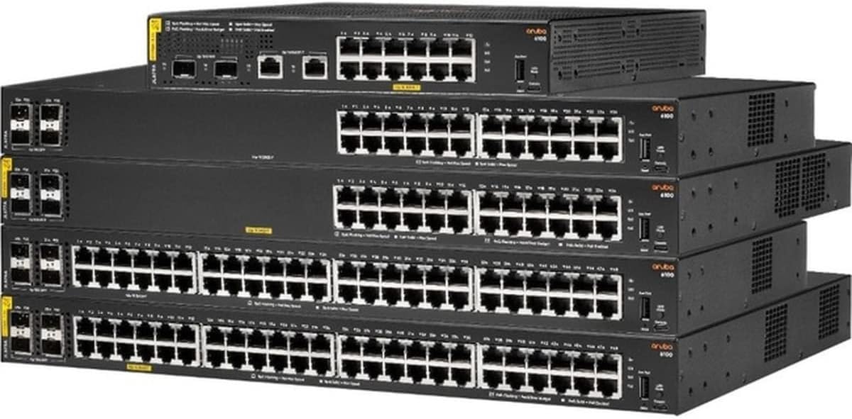
Figure 1: A stack of Aruba CX 6100 Series Switches, showcasing the front panels with various Ethernet and SFP+ ports. The top switch appears to be a smaller model, while the lower switches are larger, likely 24-port or 48-port versions, all featuring the Aruba branding and model series.
4.1 Front Panel Features
- 24 x 10/100/1000BASE-T Ports: RJ-45 ports for standard Ethernet connections.
- 4 x 1/10GbE SFP+ Ports: For high-speed fiber or copper uplinks.
- LED Indicators: System status, port status, and PoE status.
4.2 Rear Panel Features
- AC Power Connector: For connecting the power cord.
- Grounding Screw: For chassis grounding.
- Ventilation Openings: For heat dissipation.
5. Setup
5.1 Physical Installation
The Aruba CX 6100 switch can be installed in a standard 19-inch equipment rack or mounted on a wall.
5.1.1 Rack Mounting
- Attach the provided rack-mount brackets to the sides of the switch using the screws supplied.
- Secure the switch into the rack using appropriate rack screws. Ensure the switch is level and securely fastened.
5.1.2 Wall Mounting (if applicable)
- Identify a suitable mounting location on a sturdy wall.
- Use the wall-mount template (if provided) to mark drilling points.
- Drill pilot holes and insert appropriate wall anchors.
- Secure the switch to the wall using mounting screws, ensuring it is firmly attached.
5.2 Connecting Power
- Ensure the power switch (if present) is in the OFF position.
- Connect the supplied AC power cord to the power connector on the rear panel of the switch.
- Plug the other end of the power cord into a grounded electrical outlet.
- Turn the power switch to the ON position. The system LED should illuminate.
5.3 Connecting Network Cables
- Ethernet Ports: Connect standard RJ-45 Ethernet cables from your network devices (computers, servers, access points) to the 10/100/1000BASE-T ports on the switch.
- SFP+ Uplink Ports: Insert compatible SFP+ transceivers (not included) into the SFP+ slots. Connect fiber optic or direct attach copper (DAC) cables from the transceivers to your core network devices or other switches.
6. Operating
6.1 Initial Configuration
Upon initial power-up, the switch will perform a self-test. You can access the switch's management interface via a console port (if available) or through a web browser using its default IP address (refer to the Quick Start Guide for default IP and login credentials).
- Connect a console cable to the console port and a computer. Use a terminal emulator (e.g., PuTTY) with appropriate settings (e.g., 9600 baud, 8 data bits, no parity, 1 stop bit, no flow control).
- Alternatively, connect a computer to any Ethernet port on the switch and configure your computer's IP address to be in the same subnet as the switch's default IP. Open a web browser and navigate to the switch's default IP address.
- Follow the on-screen prompts or command-line interface to change default passwords, configure IP settings, and set up basic network parameters.
6.2 Basic Network Connectivity
After initial configuration, verify network connectivity:
- Ensure all connected devices are powered on and their network adapters are enabled.
- Check the link/activity LEDs on the switch ports and connected devices. A solid green or amber light typically indicates a valid link, while blinking indicates activity.
- Test connectivity by pinging other devices on the network or accessing network resources.
6.3 LED Indicators
The switch features various LED indicators to provide real-time status information:
| LED | Status | Description |
|---|---|---|
| System LED | Solid Green | Device is powered on and operating normally. |
| Blinking Green | System is booting or performing diagnostics. | |
| Solid Amber | System error or fault. | |
| Port Link/Activity LED | Solid Green | Link established at Gigabit speed. |
| Solid Amber | Link established at 10/100 Mbps speed. | |
| Blinking Green/Amber | Data activity on the port. | |
| Off | No link or port disabled. | |
| PoE LED (if applicable) | Solid Green | PoE power is being supplied. |
| Blinking Amber | PoE fault or overload. |
7. Maintenance
7.1 Firmware Updates
Regularly check the Aruba support website for the latest firmware updates. Keeping your switch's firmware up-to-date ensures optimal performance, security, and access to new features. Follow the instructions provided with the firmware package for the update procedure.
7.2 Cleaning
To maintain proper ventilation and prevent overheating, periodically clean the exterior of the switch and its ventilation openings.
- Disconnect power to the switch before cleaning.
- Use a soft, dry cloth to wipe down the exterior surfaces.
- Use compressed air to clear dust from ventilation openings. Do not use liquid cleaners or abrasive materials.
8. Troubleshooting
This section provides solutions to common issues you might encounter.
- No Power: Ensure the power cord is securely connected to both the switch and a working electrical outlet. Check the power switch position.
- No Link on Port: Verify that the Ethernet cable is properly connected at both ends. Check the cable for damage. Ensure the connected device is powered on and its network interface is active.
- Slow Network Performance: Check for excessive network traffic or loops. Ensure duplex settings match between the switch port and the connected device. Consider upgrading firmware.
- Cannot Access Management Interface: Verify your computer's IP address is in the same subnet as the switch. Check physical connectivity. Reset the switch to factory defaults if necessary (refer to advanced documentation for this procedure).
- PoE Device Not Powering On: Ensure the device is PoE-compatible. Check the PoE LED status for faults. Verify the switch's PoE budget is not exceeded.
9. Specifications
Key technical specifications for the Aruba CX 6100 24G 4SFP+ Switch (JL678A#ABA):
| Feature | Detail |
|---|---|
| Model | JL678A#ABA |
| Ports | 24 x 10/100/1000BASE-T, 4 x 1/10GbE SFP+ |
| Switching Capacity | 56 Gbps (non-blocking) |
| Throughput | 41.6 Mpps |
| PoE Power (if applicable) | Up to 370W (total) |
| Form Factor | 1U Rack Mountable, Wall Mountable |
| Dimensions (H x W x D) | 1.73 H x 17.40 W x 7.92 D inches |
| Weight | 5.78 pounds (Item Weight) / 8.35 pounds (Product Description Weight) |
| Operating System | AOS-CX |
| Layer Support | Layer 2, with Layer 3 static routing support |
| Environmental | Environmentally Friendly Yes |
10. Warranty and Support
This Aruba product is backed by a manufacturer's warranty. For detailed warranty information, including terms and conditions, please refer to the official Aruba website or the warranty documentation included with your product. Technical support and additional resources are available through Aruba's customer support channels.
For the latest support information, software downloads, and documentation, visit the official Aruba support portal: www.arubanetworks.com/support/