1. Introduction
This manual provides comprehensive instructions for the installation, operation, and maintenance of the CAME ATS 24V Swing Gate Automation Kit, model 8K01MP-024. This kit is designed to automate swing gates with up to two leaves, each measuring up to 3 meters in length and weighing up to 400 kg.
Please read this manual thoroughly before beginning installation or operation to ensure safe and correct use of the product. Keep this manual for future reference.

Figure 1.1: Complete CAME ATS 24V Swing Gate Automation Kit contents, including two linear motors, a control panel box, a flashing light, photocells, a remote control, and various mounting hardware.
2. Safety Information
Always prioritize safety during installation, operation, and maintenance. Failure to follow safety instructions can result in serious injury or damage to property.
- Installation must be performed by qualified personnel in compliance with local regulations and standards.
- Disconnect power before performing any maintenance or troubleshooting.
- Ensure all safety devices (photocells, emergency stops) are correctly installed and functioning.
- Do not allow children to play near the gate or with the remote controls.
- Regularly inspect the system for signs of wear or damage.
- In case of emergency, use the manual release system to open the gate.
3. Kit Components
The CAME ATS 24V kit typically includes the following main components:
- 2 x Irreversible Gearmotors: These are the linear actuators responsible for opening and closing the gate leaves.
- 1 x Control Panel: Houses the electronic board for system management, programming, and integrated radio decoding.
- 1 x IP54 Wall Box: Enclosure for the control panel, providing protection against dust and water splashes.
- 1 x 4-Channel Rolling Code Remote Control: For wireless operation of the gate.
- 1 x Pair of Outdoor Photocell Sensors: Safety devices that detect obstacles in the gate's path.
- 1 x Radio Frequency Card: For enhancing remote control signal reception.
- 1 x LED Flashing Indicator: Provides visual warning during gate operation.
- Mounting Hardware: Screws, bolts, and brackets for installation.

Figure 3.1: A single CAME ATS 24V gearmotor, a robust linear actuator designed for swing gate automation.

Figure 3.2: The blue 4-channel rolling code remote control included in the kit for convenient gate operation.

Figure 3.3: A pair of CAME outdoor photocell sensors, essential safety devices that detect obstacles in the gate's path.

Figure 3.4: The CAME LED flashing indicator, which provides a visual warning when the gate is in motion.
4. Setup and Installation
Proper installation is crucial for the performance and safety of your gate automation system. Refer to the detailed technical drawings and wiring diagrams provided with your physical product for precise measurements and connections.
4.1 Pre-Installation Checks
- Ensure the gate structure is sound, well-balanced, and moves freely without friction.
- Verify that the gate hinges are in good condition and allow for smooth operation.
- Confirm power supply (24V DC) is available at the installation site.
4.2 Mounting the Gearmotors
The gearmotors should be mounted securely to the gate pillars and gate leaves. Pay close attention to the 'C' dimension (distance from the hinge pivot to the motor mounting point on the pillar) as specified in the technical drawings. For this model, the maximum 'C' distance is 200 mm.

Figure 4.1: Technical drawing illustrating the dimensions of the CAME ATS 24V gearmotor, including its overall length and extension.

Figure 4.2: Diagram showing the critical 'C' dimension for proper installation of the gate opener, indicating the maximum allowable distance from the gate hinge.
4.3 Electrical Connections
Connect the gearmotors, control panel, photocells, flashing light, and other accessories according to the wiring diagram provided with your control unit. The control panel features an integrated display, separate terminals, and integrated radio decoding for ease of wiring and programming.
4.4 Programming and Configuration
The control board allows for easy programming. Follow the on-screen prompts to set up gate parameters, including opening/closing limits, slowdowns, and safety device functions. The integrated encoder ensures precise control and smooth operation.
5. Operating Instructions
Once installed and programmed, your CAME ATS 24V system is ready for operation.
5.1 Normal Operation
- Press a button on the remote control to open or close the gate.
- The flashing light will activate during gate movement.
- The system features obstacle detection for enhanced safety, automatically reversing or stopping if an obstruction is detected.

Figure 5.1: An installed CAME ATS 24V swing gate automation system, showing the linear motor attached to the gate and pillar, with the flashing light visible in the background.
5.2 Manual Release
In case of power failure or system malfunction, the gate can be operated manually using the release mechanism on the gearmotor. This system allows you to disengage the motor and open the gate by hand.
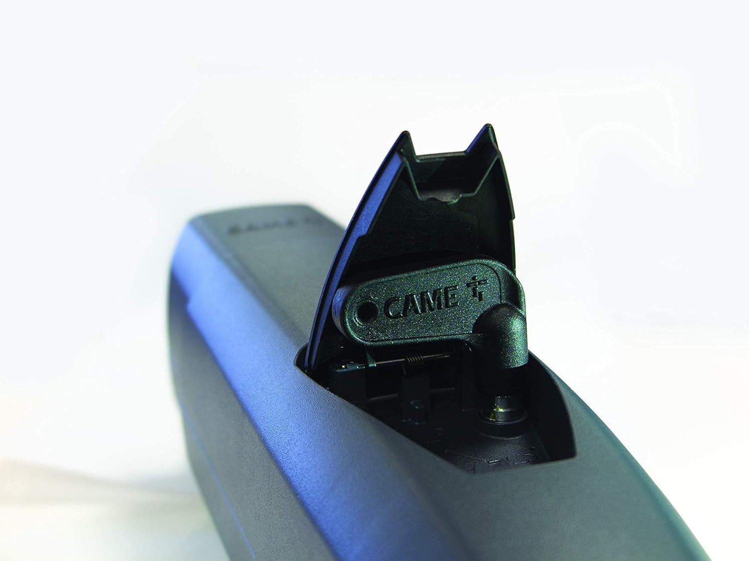
Figure 5.2: Close-up view of the manual release mechanism on the CAME ATS 24V gearmotor, allowing for manual gate operation during power outages or malfunctions.
6. Maintenance
Regular maintenance ensures the longevity and reliable operation of your CAME ATS 24V system.
- Monthly: Check the gate's mechanical movement for any obstructions or increased friction. Clean photocell lenses.
- Quarterly: Inspect all electrical connections for corrosion or looseness. Verify the functionality of safety devices (photocells, emergency stops).
- Annually: Have a qualified technician perform a thorough inspection of the motors, control unit, and all mechanical components.
- Keep the area around the gate clear of debris.
7. Troubleshooting
This section provides solutions to common issues. For complex problems, contact qualified technical support.
| Problem | Possible Cause | Solution |
|---|---|---|
| Gate does not respond to remote control. | No power; remote control battery low; remote control not programmed; photocells obstructed. | Check power supply; replace remote battery; reprogram remote; clear photocell path. |
| Gate opens partially or stops unexpectedly. | Obstruction detected; limit switch issue; motor overload. | Remove obstruction; check limit switch settings; allow motor to cool down. |
| Flashing light not working. | Bulb faulty; wiring issue. | Check bulb; inspect wiring connections. |
| Gate makes unusual noises. | Lack of lubrication; worn mechanical parts; obstruction. | Lubricate moving parts; inspect for worn components; check for obstructions. |
8. Specifications
| Feature | Detail |
|---|---|
| Model | 8K01MP-024 |
| Brand | CAME |
| Power Supply | 24V DC |
| Max Gate Leaf Length | 3 meters (per leaf) |
| Max Gate Leaf Weight | 400 kg (per leaf) |
| Motor Type | Irreversible Gearmotor with Encoder |
| Control Technology | CAME Connect (for digital control via smartphone) |
| Safety Features | Obstacle Detection, Manual Release, Photocell Compatibility |
| Enclosure Rating | IP54 (Control Panel Box) |
| Weight | 17 Kilograms (total kit) |
9. Warranty and Support
For warranty information and technical support, please refer to the documentation provided with your purchase or contact your authorized CAME dealer. Keep your proof of purchase for warranty claims.
CAME products are designed for durability and reliability. In case of any issues, professional assistance is recommended to ensure proper diagnosis and repair.