1. Introduction
This manual provides essential information for the safe and effective operation of your Hantek DSO2C10 Digital Storage Oscilloscope. Please read this manual thoroughly before using the device and keep it for future reference. The Hantek DSO2C10 is a 2-channel, 100MHz bandwidth digital storage oscilloscope designed for various electrical testing and measurement applications.
2. Safety Information
Always observe the following safety precautions to prevent injury and avoid damage to the instrument or any connected devices.
- Do not open the instrument casing. Hazardous voltage is present inside. Servicing should only be performed by qualified personnel.
- Ensure the power supply voltage matches the instrument's requirements.
- Use only the power cord and accessories supplied or specified by Hantek.
- Do not operate the instrument in wet or damp conditions.
- Avoid operating in explosive atmospheres.
- Connect the ground terminal of the probe to earth ground before connecting the probe to the circuit under test.
- Disconnect power to the circuit under test before making or breaking connections.
- Maximum input voltage: 300VRMS (10X probe attenuation). Exceeding this limit can damage the device.
3. Package Contents
Verify that all items listed below are included in your package. If any items are missing or damaged, please contact your supplier.
- 1 x Hantek DSO2C10 Digital Storage Oscilloscope
- 1 x USB Data Cable
- 1 x Test Probe (Clip Line)
- 1 x Power Cable
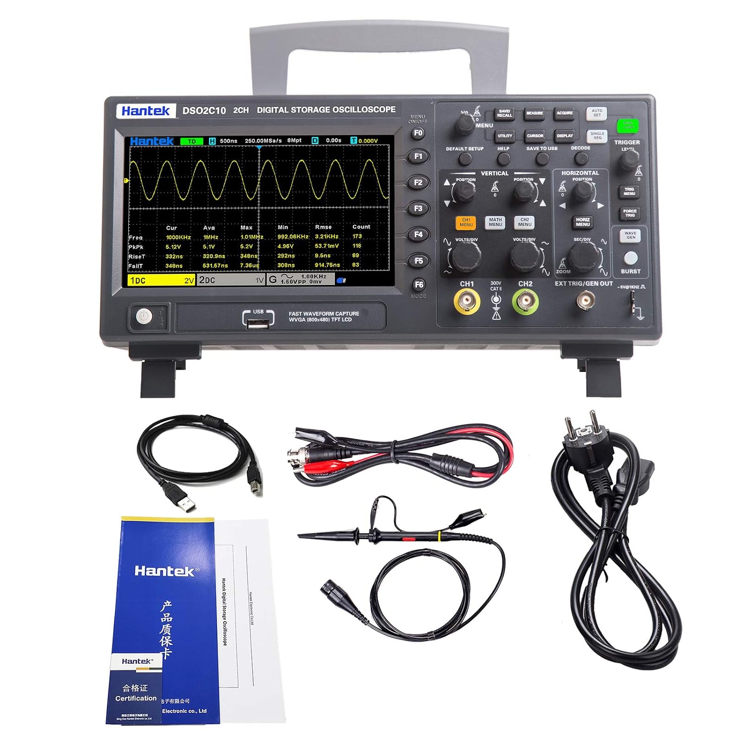
Figure 3.1: Hantek DSO2C10 Oscilloscope with its standard accessories, including the USB cable, test probe, and power cable.
4. Product Overview
4.1 Front Panel
The front panel features the LCD display, control buttons, input channels, and various function keys for operating the oscilloscope.

Figure 4.1: Detailed view of the Hantek DSO2C10 front panel, highlighting the LCD Display, Option Buttons (F1-F6), Executive Controls (e.g., MENU, UTILITY, CURSOR, DISPLAY, SAVE TO USB, DECODE, TRIGGER LEVEL), Vertical and Horizontal controls, Analog Channel Input Signals (CH1, CH2), External Trigger Input Channel, USB Interface, and Power Switch.
4.2 Rear Panel
The rear panel includes the power input and ventilation.
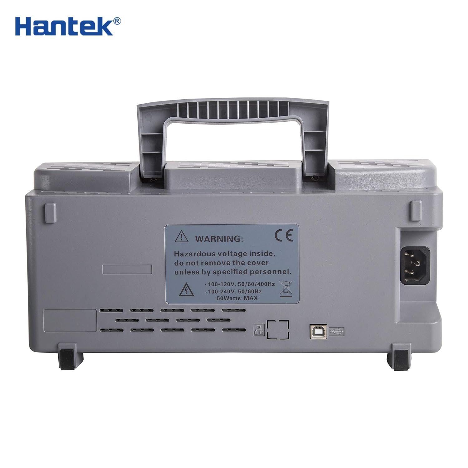
Figure 4.2: Rear view of the Hantek DSO2C10, displaying the AC power inlet, USB ports, and ventilation grilles. A warning label regarding hazardous voltage is also visible.
4.3 Side Panel
The side panel provides additional ventilation and structural support.
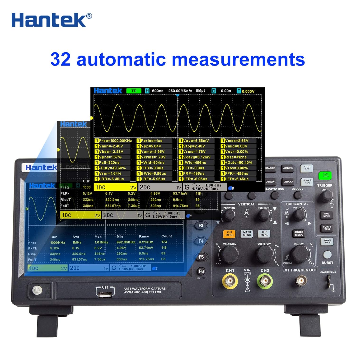
Figure 4.3: Side view of the Hantek DSO2C10, showing the robust casing and ventilation slots designed for heat dissipation.
5. Setup
- Power Connection: Connect the provided power cable to the AC power inlet on the rear panel of the oscilloscope and then to a suitable power outlet.
- Power On: Press the power switch located on the front panel to turn on the oscilloscope.
- Probe Connection: Connect the test probe to one of the analog input channels (CH1 or CH2) on the front panel. Ensure the probe's ground clip is securely connected to the ground of the circuit under test.
- Probe Compensation: Before taking measurements, compensate the probe to ensure accurate readings. Connect the probe to the probe compensation output (usually a square wave signal) and adjust the probe's compensation trimmer until a flat-top square wave is displayed on the screen.
6. Operating Instructions
6.1 Basic Operation
- Channel Selection: Use the CH1/CH2 buttons to enable or disable channels and access their settings.
- Vertical Scale (VOLTS/DIV): Adjust the vertical scale using the dedicated knob for each channel to control the voltage per division displayed on the screen.
- Vertical Position: Use the vertical position knob to move the waveform up or down on the screen.
- Horizontal Scale (SEC/DIV): Adjust the horizontal scale knob to control the time per division, affecting the time base of the waveform.
- Horizontal Position: Use the horizontal position knob to move the waveform left or right on the screen.
- Trigger Level: Adjust the trigger level knob to stabilize the waveform display. The trigger point determines where the waveform capture begins.
- Auto Set: Press the 'AUTO SET' button for automatic adjustment of vertical, horizontal, and trigger settings to display a stable waveform.
6.2 Measurement Functions
The DSO2C10 offers a variety of measurement and analysis capabilities:
- Automatic Measurements: The device supports 32 types of automatic measurements, including maximum, minimum, peak-to-peak, frequency, period, rise time, fall time, and more. Access these via the 'MEASURE' menu.
- Cursor Measurements: Use horizontal and vertical cursors to manually measure voltage and time differences on the waveform.
- Digital Voltmeter (DVM): Features a 5-bit digital voltmeter and a 6-bit hardware frequency indicator for precise readings.
- Protocol Decoding: Supports decoding and analysis for RS232/UART, I2C, SPI, CAN, and LIN protocols.
- FFT Function: Perform Fast Fourier Transform (FFT) to analyze the frequency components of a signal.
6.3 Data Storage and Connectivity
- Save Data: The oscilloscope can save data in multiple formats, including settings, waveform data, reference waveforms, CSV files, and images. Use the 'SAVE TO USB' button for quick storage to a USB drive.
- USB Interface: Connect to a computer via the USB host/device interface for data transfer and remote control using SCPI commands.
7. Maintenance
- Cleaning: Clean the instrument's exterior with a soft, damp cloth. Do not use abrasive cleaners or solvents. Ensure the device is powered off and unplugged before cleaning.
- Ventilation: Keep the ventilation openings clear of dust and obstructions to ensure proper airflow and prevent overheating.
- Storage: When not in use, store the oscilloscope in a dry, dust-free environment away from direct sunlight and extreme temperatures.
- Calibration: Periodic calibration by qualified service personnel is recommended to maintain measurement accuracy.
8. Troubleshooting
This section provides solutions to common issues. For problems not listed here, please contact Hantek customer support.
- No Power: Ensure the power cable is securely connected to both the oscilloscope and the power outlet. Verify the power outlet is functional. Check the power switch position.
- No Waveform Display: Check if the input channel is enabled. Verify the probe is correctly connected and compensated. Adjust the vertical (VOLTS/DIV) and horizontal (SEC/DIV) scales. Use the 'AUTO SET' function. Ensure the trigger level is set appropriately.
- Unstable Waveform: Adjust the trigger level and trigger source. Check the trigger mode (e.g., Edge, Pulse). Ensure the input signal is within the oscilloscope's measurement range.
- Incorrect Measurements: Verify probe attenuation settings match the physical probe (1X, 10X, etc.). Perform probe compensation. Ensure the input coupling (AC/DC/GND) is appropriate for the signal being measured.
9. Specifications
The following table details the technical specifications of the Hantek DSO2C10 Digital Storage Oscilloscope.
| Feature | Specification |
|---|---|
| Model | DSO2C10 |
| Channels | 2CH |
| Bandwidth | 100 MHz |
| Sample Rate | 1 GSa/s (single channel), 500 MSa/s (two channels) |
| Memory Depth | 8M |
| Vertical Range | 2mV/div ~ 10V/div |
| Vertical Resolution | 8 bits (up to 12 bits high resolution) |
| Input Coupling | DC, AC, GND |
| Input Impedance | 1MΩ ± 2% || 20pF ± 3pF |
| Probe Attenuation Factor | 1×, 10X, 100X, 1000X |
| Maximum Input Voltage | 300VRMS (10X) |
| Voltage Class | 300V CAT II |
| Trigger Types | Edge, Pulse Width, Video, Slope, Overtime, Window, Pattern, Interval, Delay, UART, LIN, CAN, SPI, IIC |
| Protocol Decoding | RS232/UART, I2C, SPI, CAN, LIN |
| Automatic Measurements | 32 types with statistics (Max, Min, Std Dev, etc.) |
| Digital Voltmeter | 5-bit DVM, 6-bit hardware frequency indicator |
| Data Storage Formats | Settings, Waveform, Reference Waveform, CSV, Image |
| External Interfaces | USB Host/Device |
| Remote Control | SCPI commands |
| Display Type | 7" TFT LCD display diagonally |
| Dimensions | 318 x 140 x 150 mm (approximate) |
| Weight | 2.61 kg (approximate) |
9.1 Model Comparison
For reference, here is a comparison of the DSO2C10 with other Hantek models:

Figure 9.1: Comparison of key specifications across different Hantek oscilloscope models, including channels, bandwidth, sample rate, storage depth, built-in signal source, rise time, display type, and oscilloscope size.
10. Warranty and Support
Hantek products are designed for reliability and performance. For warranty information, please refer to the documentation provided with your purchase or contact your local Hantek distributor. For technical support, troubleshooting assistance, or service inquiries, please visit the official Hantek website or contact their customer service department.