
1. Introduction
The Ocean Controls N323-RHT-485 is a digital controller designed for precise measurement and control of relative humidity and temperature. It features three independent relay outputs that can be configured for control or alarm functions, applicable to either temperature or relative humidity. This manual provides essential information for the proper installation, operation, and maintenance of your N323-RHT-485 controller.
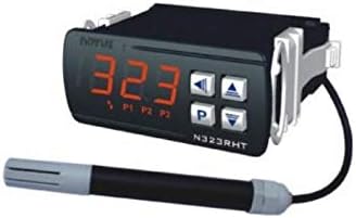
Figure 1: N323-RHT-485 Controller with its RHT sensor probe. The controller features a digital display and control buttons, while the probe is connected via a cable.
2. Key Features
- Integrated RHT sensor probe with a 3-meter cable for flexible placement.
- Three independent relay outputs for versatile control applications.
- Bright, 3.5-digit LED display for clear indication of temperature, humidity, and relay status.
- Adjustable hysteresis and configurable setpoint limits for precise control.
- Password protection for secure configuration settings.
- IP65 front panel protection when properly installed in a panel.
- RS-485 Modbus communication for integration into building management or logging systems.
- Multiple operating modes: Heating, cooling, humidifying, drying, in-band, and out-of-band alarm modes.
- Initial blocking mode to prevent premature alarms during startup.
- Configurable delayed start to manage inrush current with multiple units.
- Temporary activation mode for timed output activation.
- Sequential activation mode for periodic toggling of an output.
3. Setup and Installation
Proper installation is crucial for the reliable operation of the N323-RHT-485 controller. Ensure all power is disconnected before proceeding with any wiring.
3.1. Wiring Diagram

Figure 2: Detailed wiring connections for the N323-RHT-485. Terminals 1-2 for mains power, 3-7 for relay outputs, 8-10 for RS-485 communication, and 11-13 for the RHT sensor input.
3.2. Power Connection (Mains)
- Connect the main power supply (240 VAC) to terminals 1 and 2.
- Ensure the power source matches the controller's specified voltage.
3.3. Relay Outputs
The controller has three relay outputs. Output 1 provides common (C), normally open (NO), and normally closed (NC) contacts. Outputs 2 and 3 provide common (C) and normally open (NO) contacts.
- Output 1: Connect to terminals 3 (C), 4 (NC), 5 (NO).
- Output 2: Connect to terminals 6 (C), 7 (NO).
- Output 3: Connect to terminals 6 (C), 7 (NO).
- These outputs can drive devices such as fans, compressors, pumps, heaters, humidifiers, or dehumidifiers.
3.4. RS-485 Communication
For Modbus RTU communication, connect to the RS-485 terminals:
- Connect RS-485 D1 to terminal 8.
- Connect RS-485 D0 to terminal 9.
- Connect RS-485 C (Common/Ground) to terminal 10.
3.5. Sensor Input
The RHT sensor probe connects to the dedicated sensor input terminals:
- Connect the sensor wires to terminals 11, 12, and 13 as indicated in the wiring diagram.
- The sensor cable length is 3 meters.
3.6. Panel Installation
When installed correctly in a panel, the front face of the N323-RHT-485 achieves an IP65 rating, providing protection against dust and water jets. Follow the manufacturer's instructions for panel cutout dimensions and mounting procedures.
4. Operation
The N323-RHT-485 controller is operated via its front panel buttons and LED display.
4.1. LED Display
The bright 3.5-digit LED display shows the current temperature, relative humidity, and the status of the three relays (P1, P2, P3 indicators).
4.2. Button Functions
The front panel typically includes navigation buttons (Up, Down, P, and possibly others) for accessing and adjusting parameters. Refer to the full product manual for detailed button functions and menu navigation.
4.3. Configuration Parameters
The controller allows for extensive configuration to suit various applications:
- Setpoints and Hysteresis: Each relay output has a configurable setpoint, hysteresis, and action (e.g., trigger above/below setpoint, within/outside ranges).
- Action Modes: Relays can be configured for heating, cooling, humidifying, or drying modes. Alarm modes (in-band and out-of-band) are also available.
- Timing Functions:
- On/Off Times: Configurable on and off times for relay outputs.
- Initial Blocking: Prevents alarms from activating until normal operation conditions are met.
- Delayed Start: Reduces inrush current when multiple controllers power up simultaneously.
- Temporary Activation: Activates an output for a maximum fixed duration.
- Sequential Activation: Toggles an output on and off for applications like mixers or agitators.
- Password Protection: Configure a password to prevent unauthorized changes to settings.
5. Maintenance
The N323-RHT-485 controller is designed for reliable operation with minimal maintenance. However, periodic checks can ensure optimal performance.
- Cleaning: Gently clean the front panel with a soft, damp cloth. Do not use abrasive cleaners or solvents.
- Sensor Care: Keep the RHT sensor probe clean and free from dust or debris. Avoid exposing the sensor to harsh chemicals or extreme physical impact.
- Wiring Inspection: Periodically inspect wiring connections for any signs of loosening or corrosion. Ensure all connections are secure.
- Calibration: While the sensor is factory calibrated, if accuracy issues are suspected, refer to the full product manual for any available calibration procedures or contact technical support.
6. Troubleshooting
This section addresses common issues you might encounter with the N323-RHT-485 controller. For more complex problems, consult the full product manual or contact technical support.
| Problem | Possible Cause | Solution |
|---|---|---|
| Display is blank | No power supply; incorrect wiring. | Check power connections to terminals 1 and 2. Ensure power source is active. |
| Incorrect temperature/humidity reading | Sensor not connected; faulty sensor; sensor placed in unsuitable environment. | Verify sensor wiring to terminals 11-13. Ensure sensor is clean and in the correct measurement area. Replace sensor if faulty. |
| Relay output not activating | Setpoint not met; hysteresis setting; relay configured incorrectly; initial blocking active. | Check setpoint and hysteresis settings. Verify relay action mode. Ensure initial blocking or delayed start conditions are met. Check wiring to output terminals. |
| Communication error (RS-485) | Incorrect wiring; wrong Modbus parameters; address conflict. | Verify RS-485 wiring (D1, D0, C). Check Modbus address, baud rate, and parity settings. |
7. Specifications
| Parameter | Value |
|---|---|
| Model | N323-RHT-485 |
| Power Supply | 240 VAC |
| Display Type | 3.5-digit LED |
| Sensor Type | RHT (Relative Humidity & Temperature) |
| Sensor Cable Length | 3 meters |
| Relay Outputs | 3 independent relays |
| Communication | RS-485 (Modbus RTU) |
| Front Panel Protection | IP65 (when panel mounted) |
| Item Weight | 12 ounces (approx. 340 grams) |
| Color | Black |
| UPC | 687181838723 |
8. Warranty and Support
For warranty information, technical support, or service inquiries, please contact Ocean Controls directly or your authorized distributor. Keep your purchase receipt for warranty claims.
Manufacturer: Electronics123.com, Inc.