1. Introduction
Thank you for choosing the Rebel MIE-RB-806R Network and Telephone Cable Tester. This device is designed to efficiently test network (RJ45) and telephone (RJ11/RJ12) cables, offering functions such as wire tracking, continuity testing, and DC voltage detection. This manual provides detailed instructions for safe and effective use of your cable tester.
2. Safety Information
- Read all instructions carefully before operating the device.
- Do not expose the device to moisture or extreme temperatures.
- Use only the specified battery type for power.
- Avoid testing live circuits with high voltage. The DC voltage detection feature is for low voltage DC circuits only.
- Keep the device out of reach of children.
- If the device is damaged, do not attempt to repair it yourself. Contact qualified service personnel.
3. Product Overview and Components
The Rebel MIE-RB-806R consists of a main transmitter unit and a remote receiver unit. It comes with various accessories to facilitate different testing needs.

Figure 3.1: Main and Remote Units (Front View)
A detailed view of the Rebel MIE-RB-806R tester, highlighting the RJ45 and RJ11/RJ12 ports on the main unit, the 'PUSH TO TEST' button, and the LED indicators for cable status. The remote unit is shown with its corresponding ports and belt clip.
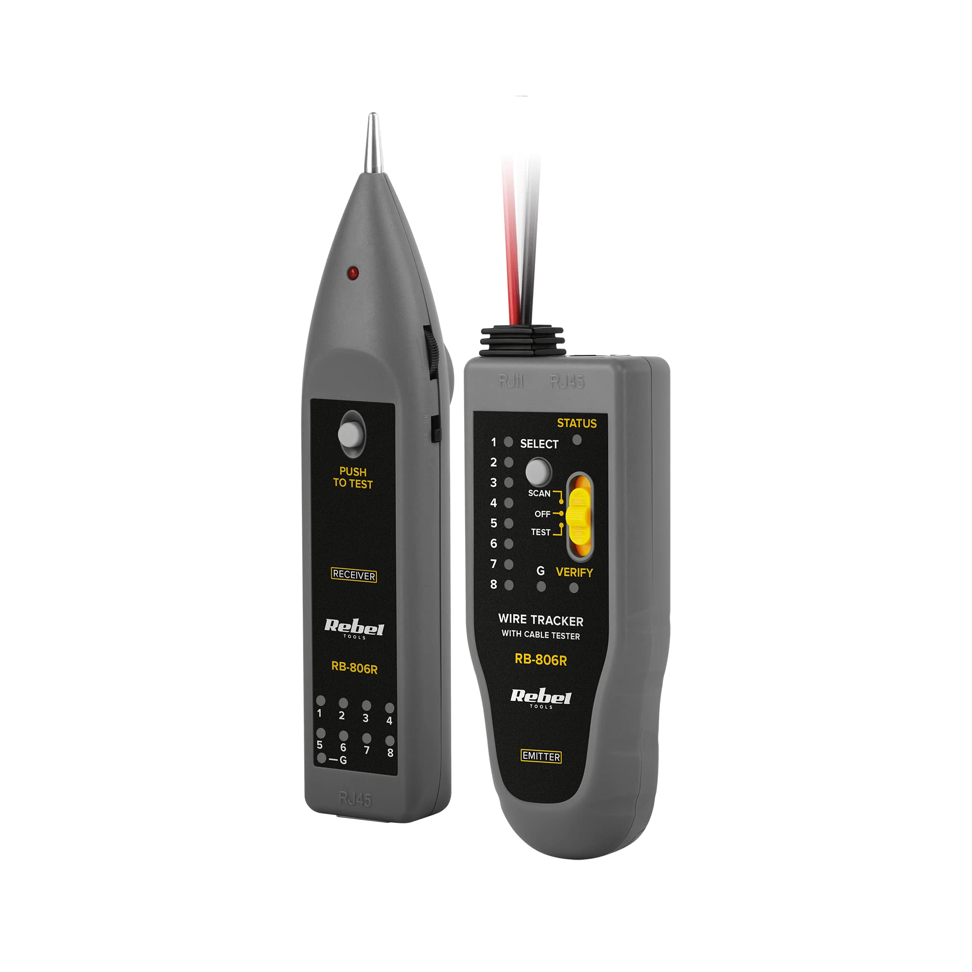
Figure 3.2: Main and Remote Units (Rear View)
This image displays the rear side of both the main and remote units of the Rebel MIE-RB-806R. It shows the battery compartment covers and labels indicating the model number and certifications.

Figure 3.3: Tester with Included Accessories
This image shows the primary components of the Rebel MIE-RB-806R cable tester, including the main transmitter unit, the remote receiver unit, and the included test cables with alligator clips and an RJ11/RJ12 connector for various testing scenarios.

Figure 3.4: Carrying Case
A red zippered carrying case, likely included with the Rebel MIE-RB-806R, designed for convenient storage and transport of the cable tester and its accessories.
Key Features:
- Wire Tracker: Locates and identifies cables.
- Crocodile Clips: For connecting to various wire types.
- Buzzer: Provides audible feedback during testing.
- Work Light: Illuminates dark work areas.
- RJ45/RJ11/RJ12 Cable Test: Verifies continuity and wiring configuration for network and telephone cables.
- DC Voltage Detector: Detects low DC voltage.
- Wire Continuity Test: Checks for breaks in wires.
4. Setup
4.1 Battery Installation
- Locate the battery compartment on the rear of both the main transmitter unit and the remote receiver unit (refer to Figure 3.2).
- Open the battery compartment cover.
- Insert the required batteries, ensuring correct polarity (+/-).
- Close the battery compartment cover securely.
4.2 Connecting Cables for Testing
Depending on the test, connect the cable to be tested to the appropriate port on the main unit and, if necessary, to the remote unit or using the alligator clips.

Figure 4.1: Common Cable Types
This image illustrates common cable types that might be tested or used in conjunction with the Rebel MIE-RB-806R, including standard RJ45 network cables and a 3.5mm audio jack, though the tester primarily focuses on network and telephone cables.
5. Operating Instructions
5.1 Network (RJ45) and Telephone (RJ11/RJ12) Cable Test
- Connect one end of the network or telephone cable to the corresponding port on the main transmitter unit.
- Connect the other end of the cable to the remote receiver unit.
- Turn on both the main and remote units.
- Press the 'PUSH TO TEST' button on the main unit.
- Observe the LED indicators on both units. The LEDs will light up sequentially, indicating the wiring configuration. Any discrepancies (e.g., open circuits, shorts, crossed pairs) will be shown by missing or out-of-sequence LEDs.
5.2 Wire Tracker Function
- Connect the cable to be traced to the main transmitter unit using the appropriate connector (RJ45, RJ11/RJ12, or alligator clips).
- Turn on the main unit and select the 'SCAN' mode.
- Turn on the remote receiver unit and use its probe to follow the cable path. The buzzer will emit a tone, which will become louder as you get closer to the correct cable.
5.3 DC Voltage Detection
- Connect the alligator clips to the main transmitter unit.
- Carefully connect the alligator clips to the DC voltage source you wish to test.
- Observe the 'V=' indicator on the main unit. If DC voltage is detected, the indicator will light up.
5.4 Wire Continuity Test
- Connect the alligator clips to the main transmitter unit.
- Connect the alligator clips to the two ends of the wire you want to test for continuity.
- If the wire has continuity (no breaks), the 'CONTINUITY' indicator or buzzer on the main unit will activate.
6. Maintenance
6.1 Cleaning
Wipe the device with a soft, dry cloth. Do not use abrasive cleaners or solvents, as they may damage the casing.
6.2 Battery Replacement
When the device's performance degrades or indicators dim, replace the batteries in both units. Refer to Section 4.1 for battery installation instructions.
6.3 Storage
Store the device in a cool, dry place, away from direct sunlight and extreme temperatures. If storing for an extended period, remove the batteries to prevent leakage.
7. Troubleshooting
- Device does not power on: Check battery installation and ensure batteries are not depleted. Replace if necessary.
- Incorrect cable test results: Ensure cables are properly connected to both the main and remote units. Verify that the cable itself is not damaged.
- Wire tracker not detecting signal: Ensure the main unit is in 'SCAN' mode and the remote unit is powered on. Check battery levels.
- No buzzer sound: Check if the buzzer feature is enabled (if applicable) and ensure batteries are sufficient.
8. Specifications
| Specification | Value |
|---|---|
| Model | MIE-RB-806R |
| Brand | Rebel |
| Power Source | Battery Powered |
| Item Weight | 214 Grams |
| Package Dimensions | 24 x 15 x 4.5 cm |
| Functions | Wire Tracking, RJ45/RJ11/RJ12 Cable Test, DC Voltage Detection, Wire Continuity Test |
9. Warranty and Support
The Rebel MIE-RB-806R Network and Telephone Cable Tester is covered by a standard manufacturer's warranty against defects in materials and workmanship. Please refer to the warranty card included with your product for specific terms and conditions.
For technical support, troubleshooting assistance, or warranty claims, please contact the retailer or manufacturer's customer service department. Keep your purchase receipt as proof of purchase.