1. Introduction
This manual provides essential information for the safe and effective operation of your ANDELI CT-520DPL Multifunctional Welder. This versatile machine combines five welding and cutting functions: CUT (Plasma Cutting), TIG (Tungsten Inert Gas) welding, PULSE TIG welding, COLD welding, and MMA (Manual Metal Arc) welding. Please read this manual thoroughly before operating the equipment.
The CT-520DPL is designed for various applications, including welding ordinary thin steel, iron, stainless steel, and low-carbon steel, as well as mold repair. It is important to note that this machine is not suitable for welding aluminum.
2. Safety Information
Welding and plasma cutting operations can be hazardous. Always follow safety precautions to prevent injury or damage. This section outlines general safety guidelines. Refer to local safety regulations and standards for comprehensive safety practices.
- Electric Shock: Can kill. Ensure proper grounding. Do not touch live electrical parts. Wear dry gloves and protective clothing.
- Fumes and Gases: Can be hazardous to health. Work in a well-ventilated area. Use fume extractors if necessary.
- Arc Rays: Can burn eyes and skin. Wear a welding helmet with appropriate shade filter and protective clothing.
- Fire and Explosion: Welding sparks and hot metal can cause fires. Keep flammable materials away from the work area. Have a fire extinguisher readily available.
- Hot Parts: Can cause severe burns. Allow equipment to cool before handling.
- Noise: Excessive noise can damage hearing. Wear hearing protection.
- Personal Protective Equipment (PPE): Always wear appropriate PPE, including welding helmet, safety glasses, gloves, protective clothing, and safety shoes.
3. Product Overview and Components
The ANDELI CT-520DPL is a compact and powerful 5-in-1 welding and cutting machine. Familiarize yourself with its main components and control panel.

Figure 3.1: Front view of the ANDELI CT-520DPL Welder, showing overall design, control panel, and key features like built-in oil water separator and gas pressure regulator. Dimensions are 430mm x 172mm x 250mm, and the unit weighs 10.7KG.
3.1 Control Panel
The control panel allows selection of welding modes and adjustment of parameters. Refer to the detailed image below for specific controls.

Figure 3.2: Detailed view of the CT-520DPL control panel. It features mode selection buttons (TIG 2T/4T, COLD, CUT 2T/4T, MMA), a digital display for parameters (HZ, %, S), a storage button, a large adjustment knob, and a pressure gauge for gas.
- Mode Selection Buttons: TIG (2T/4T), COLD, CUT (2T/4T), MMA.
- Digital Display: Shows current welding parameters (e.g., frequency, duty cycle, time).
- Parameter Adjustment Knob: Used to fine-tune settings for selected modes.
- Pressure Gauge: Displays gas pressure for TIG/COLD welding and plasma cutting.
- Storage Button: For saving or recalling welding settings.
3.2 Rear Panel Connections
The rear panel houses the main power switch, input power cable connection, gas inlet, and gas pressure adjustment knob.
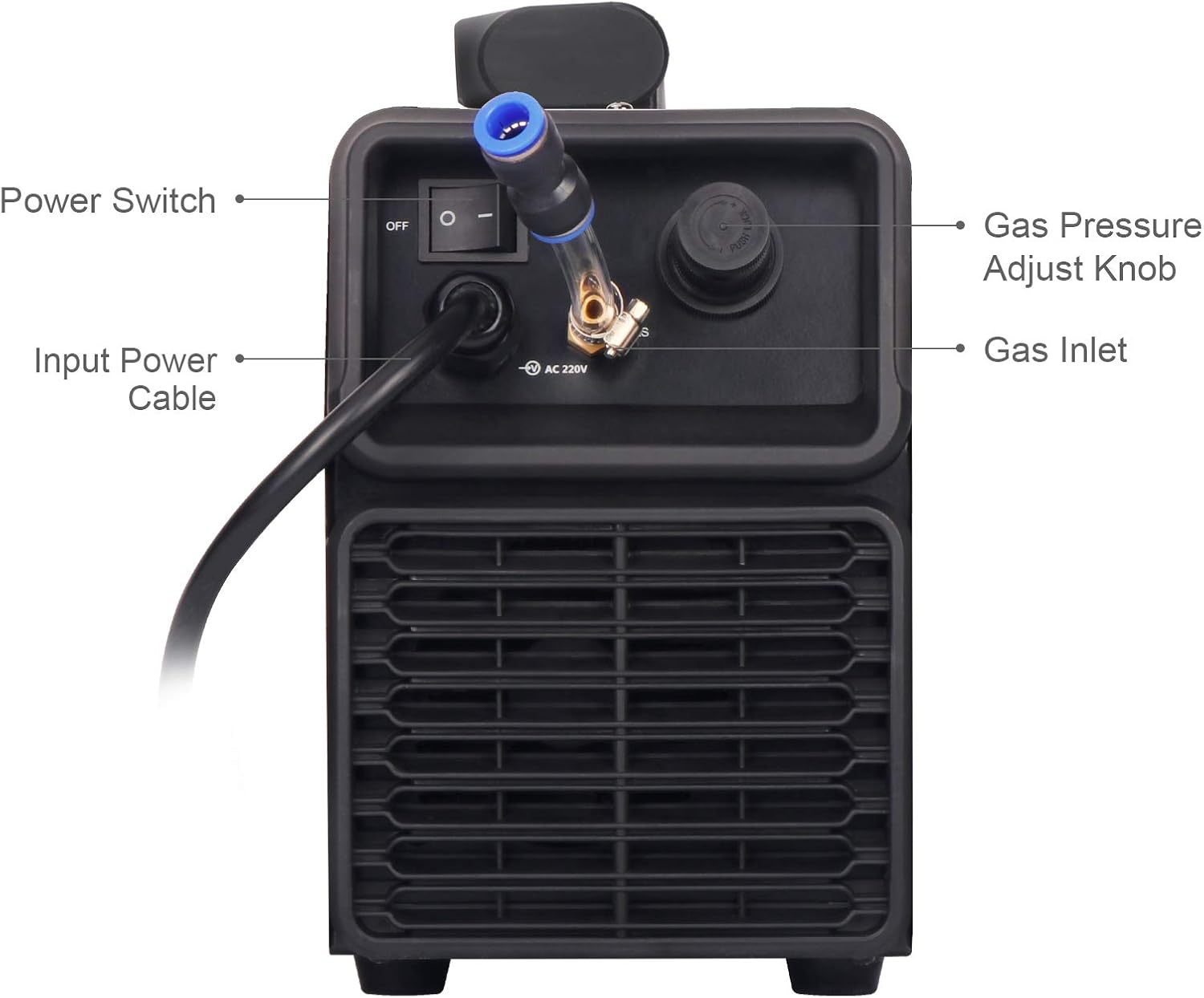
Figure 3.3: Rear view of the CT-520DPL, indicating the Power Switch, Input Power Cable, Gas Inlet, and Gas Pressure Adjust Knob.
- Power Switch: Turns the machine ON/OFF.
- Input Power Cable: Connects the welder to the 220V power supply.
- Gas Inlet: Connection point for inert gas (Argon for TIG/COLD) or compressed air (for CUT).
- Gas Pressure Adjust Knob: Used to regulate the incoming gas pressure.
4. Setup
Proper setup is crucial for safe and effective operation. Ensure all connections are secure before powering on the machine.
- Unpacking: Carefully remove the welder from its packaging. Inspect for any shipping damage.
- Power Connection: Connect the input power cable to a suitable 220V power outlet. Ensure the outlet is properly grounded and can handle the machine's power requirements.
- Ground Clamp Connection: Attach the ground clamp cable to the designated terminal on the welder and securely clamp it to the workpiece or welding table. Ensure good electrical contact.
- Torch/Gun Connection: Connect the appropriate torch (TIG torch, Plasma cutting torch, or MMA electrode holder) to its respective connection port on the front panel. Ensure connections are tight.
- Gas/Air Connection:
- For TIG/COLD welding: Connect a pure argon gas cylinder to the gas inlet on the rear panel using a suitable regulator and hose.
- For Plasma Cutting (CUT): Connect an air compressor to the gas inlet on the rear panel. The machine has a built-in oil-water separator and gas pressure regulator.
- Gas Pressure Adjustment: Adjust the gas pressure using the knob on the rear panel and monitor the gauge on the front panel to ensure correct flow for your chosen process.
- Work Area Preparation: Clear the work area of flammable materials. Ensure adequate ventilation.
Note: The CT-520DPL is sold without accessories such as a USA plug or torch. These must be acquired separately.
5. Operating Modes
The CT-520DPL offers five distinct functions. Select the desired mode using the buttons on the control panel.
5.1 CUT (Plasma Cutting)
This mode is for plasma cutting various metals. It supports 2T (two-touch) and 4T (four-touch) trigger modes. Ensure compressed air is connected and regulated.
- 2T Mode: Press and hold the torch trigger to cut; release to stop.
- 4T Mode: Press and release the trigger to start cutting; press and release again to stop. This mode is useful for longer cuts to reduce hand fatigue.
- Applicable Thickness: Up to 18mm for various metals.
5.2 TIG (Tungsten Inert Gas) Welding
TIG welding provides high-quality, precise welds. This machine features High-Frequency (HF) ignition. Pure argon gas is required.
- 2T Mode: Press and hold the torch trigger to weld; release to stop.
- 4T Mode: Press and release the trigger to start welding; press and release again to stop.
- Parameters: Adjustable parameters include Per-Flow Time, Start Current, Rise Time, Peak Current, Base Current, Down Time, Crater Current, and Post-Flow Time.
- Applicable Thickness: 0.8mm to 12mm.
5.3 PULSE TIG Welding
Pulse TIG welding offers better control over heat input, reducing distortion and improving weld quality, especially on thin materials. It uses a pulsed current between a peak and base current.
- Parameters: In addition to standard TIG parameters, Pulse Frequency and Duty Ratio are adjustable.
- Example: Pulse TIG on 0.8mm SS Square Pipe and 3mm Stainless Steel Plate (refer to Figure 5.1).
5.4 COLD Welding
COLD welding mode is designed for minimal heat input, ideal for thin materials and applications where heat distortion must be avoided. It produces a silver-white fish scale weld bead on stainless steel. Pure argon gas is required.
- Parameters: Cold Welding Time (1-200ms) and Cold Welding Interval (0-10Hz) are adjustable.
- Example: Pulse COLD on 1mm and 2mm Stainless Steel Plate (refer to Figure 5.1).
5.5 MMA (Manual Metal Arc) Welding
MMA, also known as Stick welding, is a versatile process suitable for outdoor use and on dirty or rusty materials. It uses consumable electrodes.
- Parameters: Hot-Start Current and Hot-Start Time are typically fixed or automatically controlled.
- Applicable Thickness: 2mm to 12mm.
- Example: MMA on 3.2 Stainless Steel Electrode and 4.0 Carbon Steel Electrode (refer to Figure 5.1).

Figure 5.1: Examples of weld beads and cuts achieved with the CT-520DPL in different modes: PULSE TIG (0.8mm SS Square Pipe, 3mm Stainless Steel Plate), PULSE COLD (1mm, 2mm Stainless Steel Plate), CUT (5mm Stainless Steel Plate, 6mm Aluminium Plate), and MMA (3.2 Stainless Steel Electrode, 4.0 Carbon Steel Electrode).
6. Operating Instructions
Once the machine is set up and safety precautions are in place, follow these general steps for operation:
- Power On: Turn on the main power switch located on the rear panel. The digital display on the front panel should illuminate.
- Select Mode: Press the corresponding button on the control panel for the desired welding or cutting mode (CUT, TIG, COLD, MMA).
- Adjust Parameters: Use the adjustment knob to set the current, voltage, frequency, or other parameters according to the material thickness and type, and the specific requirements of the chosen mode. Refer to the specifications table for recommended ranges.
- Test Settings: Before working on your main project, perform a test weld or cut on a scrap piece of the same material to verify settings and technique.
- Begin Operation: With appropriate PPE, begin welding or cutting. Follow proper technique for the selected process.
- Monitor Performance: Observe the arc, puddle, and cut quality. Adjust parameters as needed during operation.
- Power Off: After completing work, turn off the machine using the main power switch. Disconnect gas/air supply.
7. Maintenance
Regular maintenance ensures the longevity and optimal performance of your welder. Always disconnect power before performing any maintenance.
- Cleaning: Periodically clean the exterior of the machine with a dry, soft cloth. Do not use solvents.
- Internal Cleaning: For internal cleaning, compressed air can be used to blow out dust and debris from the cooling vents. This should be done in a well-ventilated area and with the machine disconnected from power.
- Cable Inspection: Regularly inspect all cables (power, ground, torch) for damage, cuts, or frayed insulation. Replace damaged cables immediately.
- Torch Maintenance:
- TIG Torch: Inspect and replace tungsten electrodes as needed. Ensure collets and collet bodies are clean and free of spatter.
- Plasma Torch: Check and replace consumables (electrode, nozzle, swirl ring, shield cup) regularly as they wear out.
- MMA Electrode Holder: Ensure good contact and clean any spatter.
- Gas/Air System: Check hoses and connections for leaks. Ensure the built-in oil-water separator is functioning correctly and drain any accumulated moisture if applicable.
- Storage: Store the welder in a dry, clean environment, away from excessive dust and moisture.
8. Troubleshooting
This section addresses common issues you might encounter. For problems not listed here, contact customer support.
| Problem | Possible Cause | Solution |
|---|---|---|
| Machine does not power on. | No power supply; Power switch off; Internal fuse blown. | Check power cable and outlet; Ensure power switch is ON; Contact service for fuse replacement. |
| No arc/cut in TIG/CUT mode. | No gas/air flow; Incorrect gas pressure; Poor ground connection; Worn consumables; Incorrect settings. | Check gas/air supply and pressure; Ensure ground clamp is secure; Replace torch consumables; Adjust welding parameters. |
| Poor weld quality (porosity, lack of fusion). | Insufficient shielding gas; Contaminated workpiece; Incorrect current/voltage; Improper technique. | Check gas flow and purity; Clean workpiece thoroughly; Adjust parameters; Review welding technique. |
| Overheating/Thermal overload. | Exceeding duty cycle; Blocked ventilation; High ambient temperature. | Allow machine to cool; Ensure clear ventilation; Reduce duty cycle or work in cooler environment. |
| Digital display shows error code. | Internal fault. | Note the error code and contact customer support. |
9. Specifications
Technical specifications for the ANDELI CT-520DPL Multifunctional Welder.

Figure 9.1: Comprehensive technical specifications table for the CT-520DPL, detailing parameters for TIG, COLD, CUT, and MMA functions.
| Parameter | Value |
|---|---|
| Manufacturer | ANDELI |
| Model Number | CT-520DPL |
| Rated Input Voltage | AC 220V ±15% |
| Frequency | 50/60Hz |
| Efficiency | 80% |
| Power Factor | 0.75 |
| No-Load Voltage | 64V |
| Protection Class | IP21S |
| Insulation Class | H |
| Cooling | FAN |
| Dimensions (L×W×H) | 430mm × 172mm × 250mm |
| Net Weight | 10.7 KG |
| TIG Welding Current Range | 5-200A |
| COLD Welding Current Range | 10-200A |
| CUT Current Range | 20-50A |
| MMA Welding Current Range | 10-200A |
| Welding Thickness (TIG) | 0.8-12mm |
| Cutting Thickness (CUT) | 1-18mm |
| Welding Thickness (MMA) | 2-12mm |
10. Warranty and Support
ANDELI provides a warranty for the CT-520DPL Multifunctional Welder.
- Warranty Period: Two years from the date of purchase.
- Warranty Coverage: During the warranty period, ANDELI will send free replacements to replace faulty parts.
- Customer Support: For technical assistance, troubleshooting beyond this manual, or warranty claims, please contact ANDELI customer support. Refer to your purchase documentation or the official ANDELI website for contact information.


