1. Introduction
This manual provides comprehensive instructions for the installation, operation, and maintenance of the Cisco C9200L-24T-4G-E 24-Port Full Gigabit Layer 2 Access Switch. This device is designed to provide reliable network connectivity with advanced features for various network environments.
2. Safety Information
Please read all safety warnings and instructions before installing or operating this equipment. Failure to follow these guidelines may result in injury or damage to the device.
- Ensure proper grounding for the device.
- Do not operate the device in wet or damp conditions.
- Use only the power supply provided or specified by the manufacturer.
- Avoid blocking ventilation openings to prevent overheating.
- Refer all servicing to qualified personnel.
3. Product Overview
The Cisco C9200L-24T-4G-E switch features 24 Gigabit Ethernet ports and 4 1G SFP uplink ports, designed for efficient network access and aggregation.
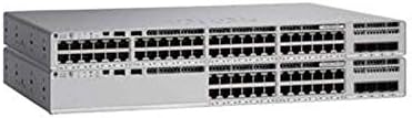
Figure 3.1: Front view of the Cisco C9200L-24T-4G-E switch, showing 24 Ethernet ports and 4 SFP uplink ports.

Figure 3.2: Angled view of the Cisco C9200L-24T-4G-E switch, highlighting the port layout and chassis design.
Front Panel Features:
- 24 x 10/100/1000Base-T Ports: For connecting network devices.
- 4 x 1G SFP Uplink Ports: For high-speed fiber or copper uplinks to other switches or routers.
- LED Indicators: System status, port status, and power indicators.
4. Setup and Installation
4.1 Unpacking
Carefully unpack the switch and verify that all components are present. Inspect the device for any signs of damage during shipping. If any items are missing or damaged, contact your vendor immediately.
4.2 Physical Installation
- Rack Mounting: The switch is designed for standard 19-inch rack mounting. Secure the switch using the provided rack-mount brackets and screws.
- Desktop Placement: If not rack-mounting, place the switch on a flat, stable surface, ensuring adequate ventilation around the device.
4.3 Connecting Power
- Connect the power cord to the AC power inlet on the rear panel of the switch.
- Plug the other end of the power cord into a grounded electrical outlet.
- Verify that the power LED on the front panel illuminates, indicating the switch is receiving power.
4.4 Network Connections
- Ethernet Ports: Connect network devices (computers, servers, other switches) to the 24 10/100/1000Base-T ports using standard Ethernet cables.
- SFP Uplink Ports: Insert compatible 1G SFP transceivers into the 4 SFP uplink ports. Connect fiber optic or copper cables from these transceivers to your core network or other switches.
5. Operating Instructions
The Cisco C9200L-24T-4G-E is a Layer 2 access switch with Layer 3 capabilities. Initial configuration typically involves accessing the switch via a console port, Telnet, SSH, or a web-based interface.
5.1 Basic Configuration
- Console Access: Connect a console cable to the console port and use a terminal emulator (e.g., PuTTY) to access the command-line interface (CLI).
- IP Address Assignment: Configure an IP address for the management VLAN interface to enable remote access.
- User Accounts: Create secure user accounts with appropriate privilege levels.
5.2 Key Features
- VLAN Support: Create and manage Virtual Local Area Networks to segment network traffic.
- QoS (Quality of Service): Prioritize critical network traffic for optimal performance.
- SNMP (Simple Network Management Protocol): Monitor and manage the switch remotely.
- LACP (Link Aggregation Control Protocol): Bundle multiple physical links into a single logical link for increased bandwidth and redundancy.
- Layer 3 Capabilities: Supports OSPF, EIGRP, ISIS, RIP, and routed access for advanced routing functionalities.
6. Maintenance
- Regular Cleaning: Keep the switch free from dust and debris. Use a soft, dry cloth for cleaning.
- Firmware Updates: Periodically check the Cisco website for firmware updates to ensure optimal performance and security.
- Environmental Control: Ensure the operating environment maintains appropriate temperature and humidity levels as specified in the product's technical specifications.
7. Troubleshooting
7.1 No Power
- Verify the power cord is securely connected to both the switch and the power outlet.
- Check the power outlet with another device to ensure it is functional.
- Ensure the power supply unit (if external) is correctly connected and functional.
7.2 No Network Connectivity
- Check the Ethernet cable connections to ensure they are secure and not damaged.
- Verify the link/activity LEDs on the switch ports are illuminated for connected devices.
- Confirm IP address settings and VLAN configurations are correct.
- Test with a different cable or port.
7.3 Slow Network Performance
- Check for network congestion or excessive broadcast traffic.
- Ensure duplex settings match between the switch and connected devices.
- Verify that QoS policies are correctly configured if prioritizing traffic.
8. Specifications
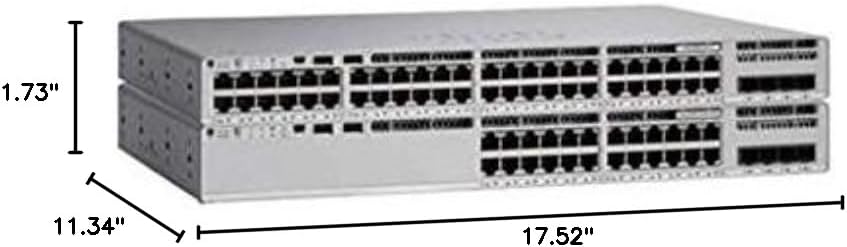
Figure 8.1: Physical dimensions of the Cisco C9200L-24T-4G-E switch.
| Feature | Description |
|---|---|
| Model Number | C9200L-24T-4G-E |
| Ports | 24 x 10/100/1000Mbps Ethernet, 4 x 1G SFP Uplink |
| Transmission Rate | 10/100/1000Mbps |
| Switching Capacity | 56 Gbps |
| Forwarding Rate | 41.66 Mpps |
| Communication Mode | Full-Duplex & Half-Duplex |
| Dimensions (W x D x H) | 44.5 x 28.8 x 4.4 cm (17.52" x 11.34" x 1.73") |
| Power Supply | PWR-C5-125WAC (Default Primary AC) |
| Layer 3 Capabilities | OSPF, EIGRP, ISIS, RIP, Routed Access |
| Certifications | FCC, CE, RoHS, ISO9001 |
| UPC | 764256220338 |
9. Warranty and Support
The Cisco C9200L-24T-4G-E switch typically comes with a 1-year warranty. For detailed warranty information, technical support, or to download the latest drivers and firmware, please visit the official Cisco website or contact your authorized reseller.
Official Cisco Store: Cisco Store on Amazon


