1. Introduction
This manual provides detailed instructions for the installation, operation, and maintenance of the Yinhing AC100V-250V 30A High Power 2-Channel Relay Module. This module is designed to control two independent loads with high or low-level DC5V trigger signals. Please read this manual thoroughly before use to ensure safe and efficient operation.
2. Safety Information
- Always disconnect power before installing or servicing the module.
- This module operates with AC100V-250V and DC5V. Improper handling can result in electric shock or damage to equipment.
- Ensure all connections are secure and correctly wired according to the diagrams.
- Do not exceed the maximum load capacity of 30A, 250V AC / 30V DC.
- Installation should be performed by qualified personnel if you are unfamiliar with electrical wiring.
- Keep the module away from moisture, dust, and extreme temperatures.
3. Product Overview
The Yinhing 2-Channel Relay Module features two independent relays capable of switching high-power AC or DC loads. It includes screw terminals for convenient wiring and jumpers for selecting high or low-level trigger modes for each channel.

Figure 3.1: Top view of the Yinhing 2-Channel Relay Module.
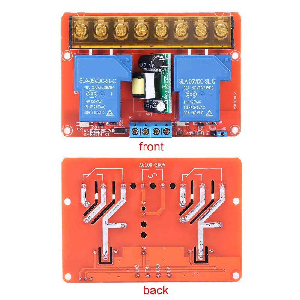
Figure 3.2: Front and back views of the relay module, illustrating component placement and circuit board layout.
The module is equipped with screw terminals for easy and secure connection of both control signals and load wiring. Jumpers allow for flexible configuration of trigger sensitivity.

Figure 3.3: Detail of the blue screw terminals for control signal input.

Figure 3.4: Detail of the yellow screw terminals for load connections.
4. Specifications
| Feature | Specification |
|---|---|
| Power Supply | AC100-250V |
| Input Control Signal Voltage (Low-level trigger) | 0-1V DC |
| Input Control Signal Voltage (High-level trigger) | 1.5-5V DC |
| Operating Current | 378mA |
| Load Capacity | 30A, 250V AC / 30V DC |
| Trigger Input DC+ | 5V |
| Trigger Input DC- | GND |
| Trigger Input CH1/CH2 | Signal Trigger Terminal |
| Manufacturer | Yinhing |
| Part Number | YINHINGpsqb435yig |
| Item Weight | 99 g |
| Wattage | 37.8 W |
| Mounting Type | Surface Mount |
| Battery Use | No |

Figure 4.1: Physical dimensions of the relay module.
5. Setup
Follow these steps to set up your relay module:
- Mounting: The module features four mounting holes for secure installation. Choose a stable, dry location away from heat sources.
- Power Supply Connection: Connect the AC100-250V power supply to the designated terminals on the module. Ensure correct polarity and secure connections.
- Load Connection: Connect your AC or DC loads to the relay output terminals. Each relay can handle up to 30A, 250V AC or 30V DC. Ensure the load current does not exceed this rating.
- Control Signal Connection: Connect your DC5V control signals to the CH1 and CH2 trigger input terminals. Connect DC+ to 5V and DC- to GND.
- Trigger Level Selection: Use the jumpers on the module to select either high-level or low-level triggering for each channel independently. Refer to the operating instructions for details on jumper settings.
6. Operating Instructions
The relay module can be configured for high-level or low-level triggering using onboard jumpers. This allows flexibility in integrating with various control systems.
- High-Level Trigger: When configured for high-level triggering, the relay will activate (switch) when the input control signal voltage on CH1 or CH2 is between 1.5V and 5V DC.
- Low-Level Trigger: When configured for low-level triggering, the relay will activate (switch) when the input control signal voltage on CH1 or CH2 is between 0V and 1V DC.
To change the trigger level, carefully adjust the corresponding jumper on the module. Always ensure power is disconnected before making any changes to jumper settings.
7. Maintenance
The Yinhing Relay Module is designed for reliable operation with minimal maintenance. Follow these guidelines to ensure longevity:
- Cleaning: Periodically clean the module with a soft, dry cloth to remove dust and debris. Do not use liquid cleaners.
- Connection Checks: Regularly inspect all wiring connections to ensure they remain tight and free from corrosion. Loose connections can lead to intermittent operation or overheating.
- Environmental Conditions: Ensure the operating environment remains within the specified temperature and humidity ranges to prevent damage.
8. Troubleshooting
If you encounter issues with your relay module, refer to the following troubleshooting steps:
- Relay Not Activating:
- Check the main power supply to the module (AC100-250V).
- Verify the DC5V control signal is present and stable at the CH1/CH2 terminals.
- Ensure the jumper setting for the trigger level (high or low) matches your control signal.
- Inspect all wiring for loose connections or breaks.
- Load Not Receiving Power:
- Confirm the relay is activating (you may hear a click or see an indicator LED if present).
- Check the wiring between the relay output terminals and the load.
- Ensure the load itself is functional and not drawing excessive current.
- Verify the load's voltage and current requirements are within the module's specifications.
- Module Overheating:
- Ensure the load current does not exceed 30A.
- Check for proper ventilation around the module.
- Verify that the ambient temperature is not too high.
If the problem persists after following these steps, contact customer support for further assistance.
9. Warranty and Support
For warranty information or technical support, please refer to the product's purchase documentation or contact the seller directly. You can also visit the Yinhing Brand Store for more information.