1. Introduction
This manual provides essential information for the safe and effective installation, operation, and maintenance of the Axppin ZGQ1M-63/3P Mini Intelligent Dual Power Automatic Transfer Switch. Please read this manual thoroughly before installation and operation to ensure proper function and safety.
2. Safety Information
Always observe the following safety precautions to prevent personal injury or damage to the equipment.
- Installation and maintenance should only be performed by qualified electricians.
- Ensure all power sources are disconnected before installation, wiring, or maintenance.
- Verify correct voltage and current ratings before connecting the device.
- Do not operate the switch if it appears damaged.
- Wear appropriate personal protective equipment (PPE) during installation and maintenance.
- The device is designed for indoor use in a dry environment.
3. Product Overview
The Axppin ZGQ1M-63/3P is a 3-pole automatic transfer switch designed to seamlessly switch between a common power supply and a standby power supply. It features intelligent control, compact size, and robust protection functions.

Figure 3.1: Front view of the Axppin ZGQ1M-63/3P Automatic Transfer Switch.
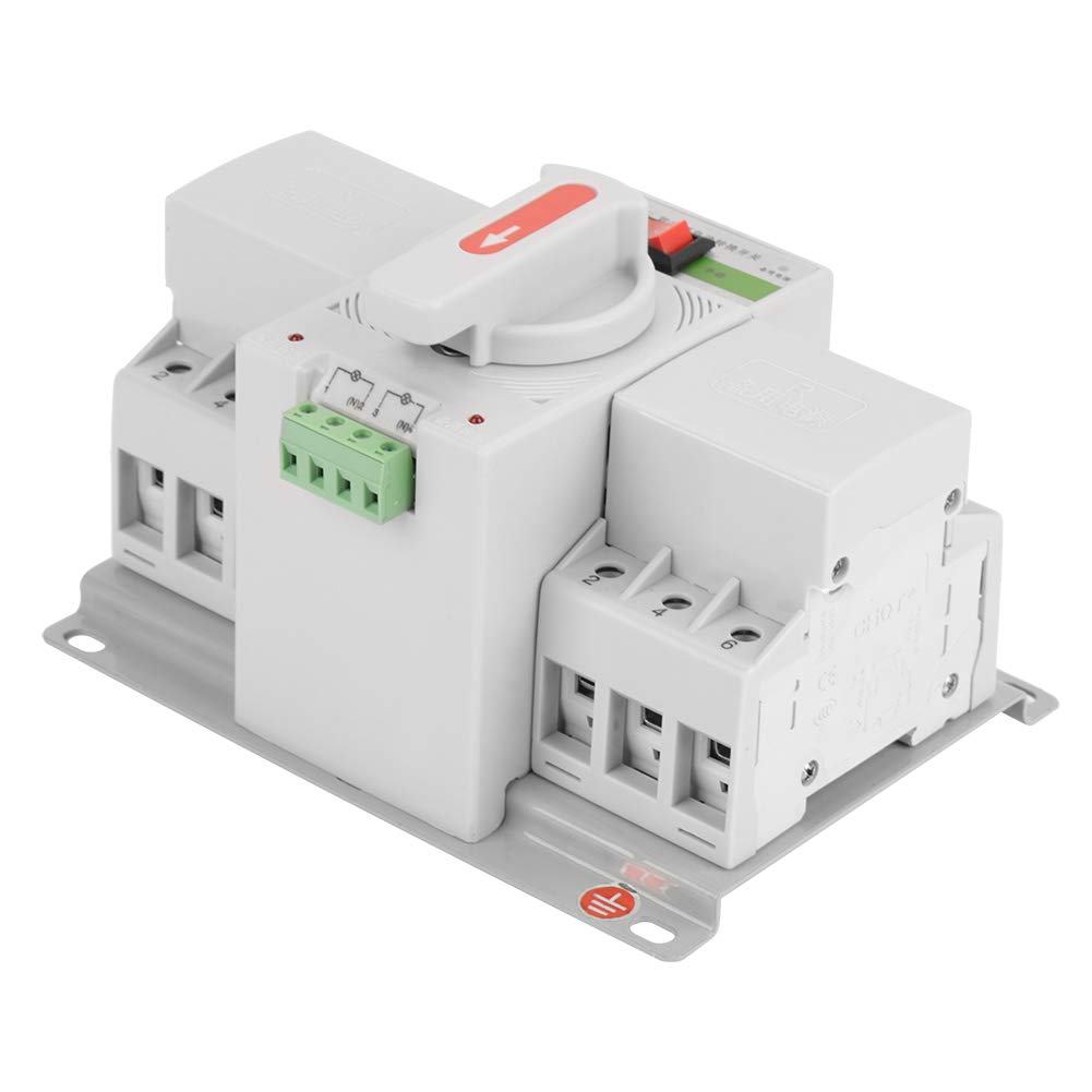
Figure 3.2: Labeled components and dimensions of the transfer switch. Key components include common power input (N), standby power input (R), automatic/manual selector, and indicator lights.

Figure 3.3: Detailed view of the terminal connections and control interface.
4. Specifications
| Feature | Specification |
|---|---|
| Model | ZGQ1M-63/3P |
| Input Voltage | 220V |
| Rated Voltage | 400V |
| Rated Current | 63A |
| Insulation Voltage | 4000V |
| Rated Impact Withstand Voltage | 4KV |
| 3C Rated Voltage Range | 37V-440V |
| EPS External Indication | DC12-24V |
| Operation Mode | Automatic |
| Contact Type | Normally Open |
| Connector Type | Screw Terminals |
| Circuit Type | 2-way |
| Actuator Type | Rotary |
| Product Dimensions (L x W x H) | 18.5 x 13.5 cm (7.28 x 5.31 inches) |
| Weight | 1700g (3.75 lbs) |
5. Installation and Setup
Proper installation is crucial for the safe and reliable operation of the automatic transfer switch. Ensure all safety precautions are followed.
5.1 Mounting
- Select a suitable location for mounting, such as an electrical panel, ensuring adequate ventilation and protection from moisture.
- The device should be mounted vertically on a stable surface using appropriate fasteners through the mounting holes.
- Ensure sufficient clearance around the switch for wiring and heat dissipation.
5.2 Wiring
Refer to the wiring diagram below for correct connections. All wiring must comply with local electrical codes and standards.
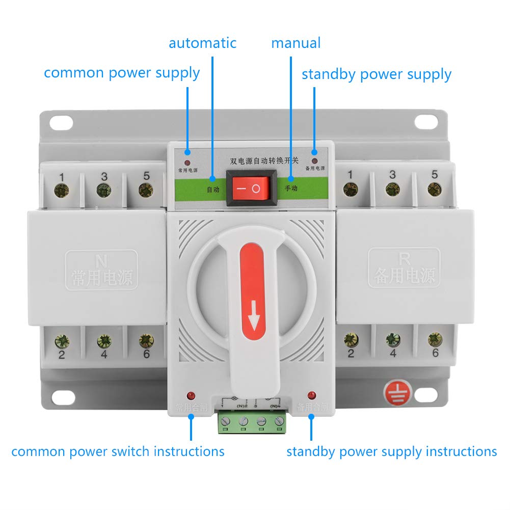
Figure 5.1: Wiring diagram for the Axppin Automatic Transfer Switch.
- Disconnect Power: Before starting any wiring, ensure both the common power supply (utility) and the standby power supply (generator, UPS, etc.) are completely disconnected and locked out.
- Connect Common Power: Connect the common power supply lines (L1, L2, L3, N for 3-phase or L1, N for single-phase) to the terminals labeled '1', '3', '5', and 'N' on the 'N' (Common Power) side of the switch.
- Connect Standby Power: Connect the standby power supply lines (L1, L2, L3, N) to the terminals labeled '1', '3', '5', and 'N' on the 'R' (Standby Power) side of the switch.
- Connect Load: Connect the load lines (L1, L2, L3, N) to the output terminals labeled '2', '4', '6', and 'N' at the bottom of the switch.
- Connect EPS Control (Optional): If using an external EPS (Emergency Power Supply) control, connect the DC12-24V control lines to the designated EPS terminals (N1, N2) as shown in Figure 3.2.
- Grounding: Ensure proper grounding of the entire system according to local electrical codes.
- Verify Connections: Double-check all connections for tightness and correctness before restoring power.
6. Operating Instructions
The Axppin ZGQ1M-63/3P offers both automatic and manual operation modes.
6.1 Automatic Mode
- Set the selector switch on the front panel to the 'Automatic' position (refer to Figure 3.2).
- In this mode, the switch will automatically detect the presence and quality of the common power supply.
- If the common power fails or falls outside acceptable parameters, the switch will automatically transfer the load to the standby power supply.
- When the common power is restored, the switch will automatically transfer the load back to the common power supply after a preset delay.
- Indicator lights on the front panel will show which power source is currently active.
6.2 Manual Mode
- Set the selector switch on the front panel to the 'Manual' position (refer to Figure 3.2).
- In manual mode, the transfer between common and standby power is controlled by the red handle.
- To switch to common power, rotate the handle towards the 'N' (Common Power) side.
- To switch to standby power, rotate the handle towards the 'R' (Standby Power) side.
- Ensure the handle is fully engaged in the desired position.
7. Maintenance
Regular maintenance helps ensure the longevity and reliable operation of the transfer switch.
- Periodic Inspection: Visually inspect the switch and its connections regularly for any signs of damage, loose wiring, or overheating.
- Cleaning: Keep the switch clean and free from dust and debris. Use a dry, soft cloth for cleaning. Do not use liquid cleaners.
- Terminal Tightness: Periodically check and tighten all terminal screws to ensure good electrical contact.
- Functional Test: If safe to do so, periodically test the automatic transfer function by simulating a power outage (e.g., by temporarily disconnecting the common power supply).
- Professional Service: For any complex issues or internal repairs, contact a qualified service technician.
8. Troubleshooting
This section provides solutions to common issues. For problems not listed here, contact technical support.
| Problem | Possible Cause | Solution |
|---|---|---|
| Switch does not transfer automatically | 1. Selector switch in 'Manual' mode. 2. Control circuit fault. 3. Power supply issues. | 1. Set selector to 'Automatic'. 2. Check DC12-24V control connections. 3. Verify both power sources are stable. |
| No power to load | 1. Both power sources unavailable. 2. Loose wiring connections. 3. Internal fault in the switch. | 1. Check common and standby power sources. 2. Inspect and tighten all terminal connections. 3. Contact qualified service personnel. |
| Overheating or burning smell | 1. Overload condition. 2. Loose connections. 3. Internal component failure. | 1. Immediately disconnect power. Reduce load. 2. Check and tighten all connections. 3. Do not operate; contact qualified service personnel. |
9. Warranty and Support
For warranty information, please refer to the terms and conditions provided at the time of purchase or contact your seller directly. For technical support or service inquiries, please reach out to Axppin customer service or your authorized distributor.