Introduction
This manual provides detailed instructions for the installation, operation, and maintenance of your ATO 2hp Single to Three Phase Variable Frequency Drive (VFD). This VFD is designed to convert single-phase 220V/230V input into three-phase output for precise speed adjustment of 3-phase AC motors. Please read this manual thoroughly before installation and operation to ensure safe and efficient use.
Important Safety Instructions
- Risk of electrical shock. Ensure proper grounding and always disconnect AC power before installation or maintenance.
- Read the manual thoroughly before installation and operation.
- Never connect AC power to output U, V, W terminals.
- Wait 10 minutes for capacitor discharge after power off before touching internal components.
- Ensure the VFD is installed in a well-ventilated area, free from dust and moisture.
Product Overview
The ATO 2hp Single to Three Phase VFD is a robust device for controlling 3-phase AC motors. It offers non-emergency start/stop control, acceleration, deceleration, and overload protection. It is suitable for machines such as conveyors, fans, and pumps which benefit from reduced and controlled motor operating speeds.
Key Features
- Input: Single phase AC 220-240V
- Output: Three phase AC 0~input voltage
- Power: 2 hp (1.5 kW)
- Provides non-emergency start & stop control, acceleration, deceleration, and overload protection.
- Reduces motor startup inrush current by gradually accelerating the motor.
Product Dimensions
5.91"L x 3.86"W x 4.49"H
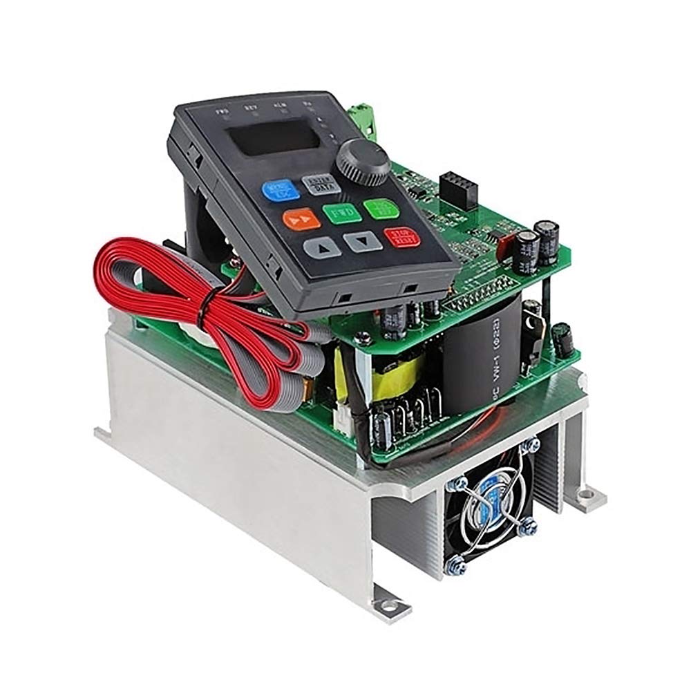
Image: Front view of the ATO 2hp Single to Three Phase VFD.
Installation and Wiring
Power Supply Connection
Connect the single-phase AC 220-240V power supply to the 'L' and 'N' terminals of the VFD. Ensure these connections are secure.

Image: Connecting the L and N terminals of the VFD to the power supply.
Motor Connection
Connect the 3-phase AC motor to the 'U', 'V', and 'W' output terminals of the VFD. Double-check these connections to ensure they are secure and follow the provided wiring diagram.

Image: Connecting the U, V, and W terminals of the VFD to the motor.
Control Switch Wiring (Single Push Button)
For single push button control, connect one normally open (NO) terminal of the self-locking push button to the X1 (FWD) terminal on the VFD. Connect the other terminal of the push button to the common (COM) input on the VFD.
Video: Detailed wiring and programming for a single push button to control VFD forward motor operation.
Multi-Stage Speed Control Wiring (Optional)
For multi-stage speed control using external buttons, connect K1, K2, K3 to X4, X5, X6 respectively, and the common line to COM. This allows for different preset speeds based on button combinations.
Video: Demonstrates wiring and programming for multi-stage speed control using external buttons.
Operation and Programming
Basic VFD Programming for Single Push Button Control
To enable control via the self-locking switch instead of the VFD's control panel, configure the following parameters:
- Set P0.01 to 1 (Main frequency source selection: Digital setting 2. This allows the VFD to hold the instant output value in case of power disconnection).
- Set P0.03 to 1 (Command source selection: Terminal control. This enables operation through control terminals).
- Set P3.00 to 1 (Input terminal X1 function selection: Forward RUN (FWD). This assigns the forward input to the self-locking push button).
- Set P3.14 to 1 (Terminal command mode: Two-line mode 2).
After programming, the VFD can be controlled by the self-locking switch. Press the button to start the motor, and press it again to stop. The VFD will retain the last output frequency setting even after power removal.
Speed Adjustment
To adjust the motor speed, simply rotate the potentiometer knob on the VFD's front panel. This will change the output frequency and regulate the motor speed.
Multi-Stage Speed Programming
To utilize multi-stage speed control with external buttons, configure the following parameters:
- P0.01=6 (defined as multi-stage speed control command)
- P3.00=1 (X1 is defined as FWD)
- P3.01=2 (X2 is defined as REV)
- P3.02=3 (X3 is defined as STOP, normally closed)
- P3.03=12 (X4 is defined as multi-speed terminal K1)
- P3.04=13 (X5 is defined as multi-speed terminal K2)
- P3.05=14 (X6 is defined as multi-speed terminal K3)
- Pb.00=15 (frequency of multi-speed 0 is 15Hz)
- Pb.01=20 (the frequency of multi-speed 1 is 20Hz)
- Pb.02=25 (the frequency of multi-speed 2 is 25Hz)
- Pb.03=30 (the frequency of multi-speed 3 is 30Hz)
- Pb.04=35 (the frequency of multi-speed 4 is 35Hz)
- Pb.05=40 (the frequency of multi-speed 5 is 40Hz)
- Pb.06=45 (the frequency of multi-speed 6 is 45Hz)
- Pb.07=50 (the frequency of multi-speed 7 is 50Hz)
Maintenance
- Regularly inspect wiring connections for tightness and signs of wear.
- Keep the VFD clean and free from dust and debris to ensure proper ventilation.
- Ensure the operating temperature does not exceed 60 Degrees Celsius.
- Periodically check for any unusual noises or vibrations from the motor or VFD.
Troubleshooting
- Motor does not start: Check all wiring connections, especially power input (L, N) and motor output (U, V, W). Verify VFD programming parameters (P0.01, P0.03, P3.00, P3.14) are correctly set for the desired control mode.
- Speed adjustment not working: Ensure P0.01 is set to 1 and the potentiometer is functioning correctly. For multi-stage control, verify the Pb parameters.
- Overload error: Check the motor's current draw and ensure it does not exceed the VFD's rated capacity. Reduce the load or adjust acceleration/deceleration times.
- For any persistent issues, refer to the full user manual included with the product or contact customer support.
Product Specifications
| Feature | Specification |
|---|---|
| Input Voltage | Single phase AC 220-240V |
| Output Voltage | Three phase AC 0~input voltage |
| Power Rating | 2 hp (1.5 kW) |
| Product Dimensions | 5.91"L x 3.86"W x 4.49"H |
| Material | Iron |
| Display Type | LCD or LED |
| Operating Temperature | 60 Degrees Celsius |
| UPC | 784104330651 |
Warranty and Customer Support
ATO is committed to customer satisfaction. If you have any questions or encounter an issue with the product or service, please do not hesitate to email us. We will respond within 12 hours.
A paper user manual is included in our package. An electronic user manual is available upon request.


