
1. Product Overview
The DollaTek CH341A USB Programmer Kit is designed for in-circuit programming of EEPROM chips, specifically 24XX/25XX series BIOS flash memory. This kit allows users to read, erase, program, and verify EEPROM chips without the need for desoldering, simplifying tasks on motherboards, routers, set-top boxes, LCD screens, and game consoles.
The kit includes a CH341A USB programmer, a SOP8 SOIC8 test clip, an 8-pin to 8-pin converter, and two SOP8/SOP16 to 8-pin converters, along with 2.54mm 4-pin headers.

Figure 1: Complete DollaTek CH341A USB Programmer Kit components.
Key Features:
- Enables in-circuit programming of EEPROM without desoldering the chip.
- Supports most 24/25 series SOP8 and SOP16 EEPROM BIOS chips.
- SOP8 test clip is compatible with both wide and narrow body SOP8 chips with a 1.27mm pitch.
- The CH341A programmer facilitates backup, erase, program, and calibration functions.
- Important Note: Due to the characteristics of the CH341A chip, some chips, such as ESMT SST class 25, may only be readable and not writable.
2. Setup Instructions
Follow these steps to set up your DollaTek CH341A USB Programmer Kit:
- Identify Components: Familiarize yourself with the CH341A programmer, SOP8 SOIC8 test clip, and various adapters (8-pin to 8-pin, SOP8/SOP16 converters).
- Connect Programmer to Adapter: If using an adapter for a specific chip package (e.g., SOP8 to DIP8), insert the adapter into the ZIF socket on the CH341A programmer.
- Connect Test Clip (if applicable): If performing in-circuit programming, connect the SOP8 test clip to the appropriate adapter or directly to the programmer via the ribbon cable. Ensure the red wire on the ribbon cable aligns with Pin 1 on both the clip and the adapter/programmer.
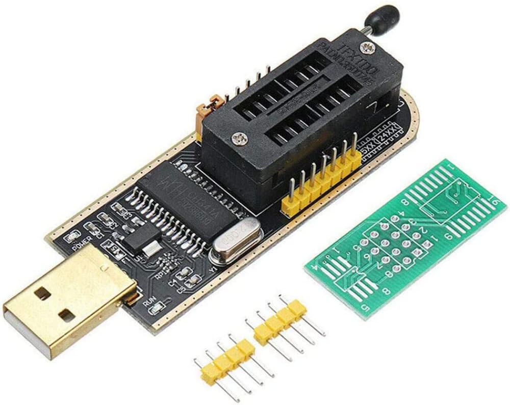
Figure 2: CH341A USB Programmer with an adapter.

Figure 3: SOP8 SOIC8 Test Clip and included adapters.
Important Considerations:
- Chip Location: Some motherboards may allow direct clipping, but certain chips are affected by peripheral circuits and cannot be used this way. Verify the chip's location on the motherboard and potential interference from surrounding components before attempting direct clipping.
- External 3.3V Supply: The test clip can be used with high-power programmers. If a programmer with a protected function is encountered, the clip might not read at normal voltage. In such cases, an external 3.3V voltage supply may be required. To apply 3.3V, hold the chip and connect the 3.3V supply to the pin corresponding to the 8th pin of the chip. Typically, the 3.3V power supply has two wires: the VCC wire connects to the clip, and the other wire is grounded.
3. Operating Instructions
This section outlines the general procedure for using the DollaTek CH341A USB Programmer Kit. Specific software instructions may vary.
Recommended Software:
Utilize compatible programming software such as NeoProgrammer (version 2.2.0.10 or later recommended) for optimal functionality. Other software may also be compatible.
Programming Procedure:
- Identify Target Chip: Locate the EEPROM chip on your circuit board that you intend to read or program.
- Attach Test Clip: Carefully open the SOP8 test clip and attach it to the target chip. Ensure proper alignment and firm contact with all pins. Do not force the clip; open it fully before attaching to avoid damaging the chip or the clip pins.
- Connect Programmer: Connect the CH341A programmer to your computer's USB port.
- Launch Software: Open your chosen programming software (e.g., NeoProgrammer).
- Select Chip Type: Within the software, select the correct manufacturer and model of the EEPROM chip you are working with.
- Perform Operation: Execute the desired operation:
- Read: To back up the existing firmware/data from the chip.
- Erase: To clear the contents of the chip before programming new data.
- Program (Write): To write new firmware/data to the chip.
- Verify: To compare the programmed data with the source file to ensure accuracy.
- Disconnect: After completing the operation, safely remove the programmer from the USB port and then carefully detach the test clip from the chip.
4. Maintenance
Proper maintenance ensures the longevity and reliable performance of your programmer kit:
- Cleanliness: Keep the programmer, test clip, and adapters clean and dry. Use a soft, dry cloth to wipe away dust or debris. Avoid using liquids or harsh chemicals.
- Storage: Store all components in a protective case or anti-static bag when not in use to prevent damage to pins and connectors.
- Handle with Care: Always handle the SOP8 test clip with care to avoid bending or breaking the delicate pins. Ensure the clip is fully open before attaching or detaching it from a chip.
- Inspect Connections: Periodically inspect the ribbon cable and connectors for any signs of wear or damage.
5. Troubleshooting
If you encounter issues while using the programmer kit, refer to the following troubleshooting tips:
- Chip Not Detected or Read Errors:
- Ensure the SOP8 test clip is correctly aligned and making firm, consistent contact with all chip pins. Gently adjust the clip if necessary.
- Verify that the correct chip type is selected in the programming software.
- Check for peripheral circuit interference. Some chips cannot be programmed in-circuit due to surrounding components. In such cases, desoldering the chip may be necessary (if feasible and you have the expertise).
- If using a high-power programmer or encountering protection features, an external 3.3V power supply might be required. Refer to the 'Setup Instructions' section for details on applying 3.3V.
- Cannot Write to Chip:
- Some chips, like ESMT SST class 25, are read-only with the CH341A programmer. Confirm the chip's compatibility for writing operations.
- Ensure the chip is not write-protected. Consult the chip's datasheet for any write protection mechanisms that may be active.
- Verify the 3.3V external power supply is correctly connected if required for writing.
- Physical Damage to Clip or Chip:
- Avoid forcing the test clip onto the chip. Always open the clip fully before attaching to prevent bending or breaking pins.
- Inspect the clip's pins for any bending or damage. A damaged clip may not make proper contact and should be replaced.
6. Specifications

Figure 4: CH341A USB Programmer with approximate dimensions.
| Feature | Detail |
|---|---|
| Brand | DollaTek |
| Model Name | SOP8 SOIC8 Test Clip |
| Model Number | 6543815031 |
| ASIN | B08HQB1VL8 |
| UPC | 705333559637 |
| Connections | USB |
| Compatible Devices | Motherboards, routers, set-top boxes, LCD screens, game consoles |
| Hardware Interface | USB |
| Write Speed | 60 MB/s |
| Connectivity Technology | USB Type A |
| Color | Black |
| Flash Memory Type | EEPROM |
7. Warranty and Support
Warranty Information: Specific warranty details for this product are not provided by the manufacturer in the available documentation. Please refer to your retailer's return policy or contact DollaTek directly for warranty inquiries.
Customer Support: For technical assistance, troubleshooting, or further information regarding the DollaTek CH341A USB Programmer Kit, please contact DollaTek customer support through their official channels or the retailer from whom the product was purchased.


