Introduction
This manual provides detailed instructions for the installation, operation, and maintenance of your Diginex HFeng Outdoor Door Access Control System Kit. This kit includes an IP68 waterproof RFID keypad, a power supply unit, a door exit button, and 10 RFID keyfobs. Please read this manual thoroughly before installation and use to ensure proper functionality and safety.

Image 1: Overview of the Diginex HFeng Outdoor Door Access Control System Kit, showing the RFID keypad, power supply, door exit button, and 10 RFID keyfobs.
Product Features
- User Capacity: Supports up to 3000 users.
- Access Methods: RFID Card, password, or a combination of RFID card + password.
- Waterproof Rating: IP68 waterproof keypad, suitable for outdoor installation.
- Backlight: Blue backlight for clear visibility in low-light conditions.
- Doorbell Function: Integrated doorbell button for wired doorbell connection.
- Wiegand Interface: WG26/34 input/output for connecting an additional card reader.
- Direct Programming: RFID cards and passwords can be programmed directly on the device without a computer.
- Power Supply: AC100V-260V input, DC12V/3A output with adjustable 0-15 second time delay.
Specifications
| Component | Specification |
|---|---|
| Access Control Keypad |
|
| Power Supply |
|
| Door Exit Button |
|
| RFID Keyfobs (10 pcs) |
|

Image 2: Detailed dimensions of the access control keypad, showing front, side, and rear measurements.

Image 3: Specifications and appearance of the door exit button and the included RFID keyfobs.
Setup and Installation
This section outlines the steps for installing your access control system. Ensure all components are present before beginning.
1. Component Identification
Familiarize yourself with the main components:
- Access Control Keypad (IP68 Waterproof)
- Power Supply Control Unit
- Door Exit Button
- 10 RFID Keyfobs
- Note: Electric lock is NOT included and must be purchased separately.
2. Mounting the Keypad
The keypad is IP68 waterproof and designed for outdoor use. Mount it at a convenient height near the door.

Image 4: The access control keypad demonstrating its IP68 waterproof capability, suitable for outdoor installation.
3. Wiring Diagram and Connections
Carefully follow the wiring diagram below. Incorrect wiring can damage the system. It is recommended to consult a qualified electrician if you are unsure about any wiring steps.

Image 5: Comprehensive wiring diagram illustrating connections between the access controller, power supply, exit button, and various types of electric locks (strike, drop, magnetic).
- Power Supply Connection: Connect the AC110-260V input to your main power source. Connect the DC12V output to the access controller and the electric lock as per the diagram.
- Keypad to Power Supply: Connect the keypad's power and signal wires to the power supply control unit.
- Exit Button Connection: Connect the door exit button to the designated terminals on the power supply control unit.
- Electric Lock Connection: Connect your electric lock (not included) to the appropriate NC (Normally Closed) or NO (Normally Open) terminals on the power supply, depending on your lock type (Fail Safe or Fail Secure).
- Jumper Position: If the keypad does not disengage the lock after correct wiring, check the jumper position on the power supply. It may need to be set to the "PUSH" pins for proper operation.
Ensure all connections are secure and insulated to prevent short circuits.
Operating Instructions
This section details how to operate your access control system, including user management and door access.
1. Initial Power-Up and Default Settings
Upon first power-up, the system will be in its default state. Refer to the keypad's specific programming manual (usually included with the keypad itself) for default master codes and initial setup procedures.
2. User Management (Adding/Deleting Users)
The system supports direct programming of RFID cards and passwords. Consult the keypad's programming guide for detailed steps on how to add or delete user RFID cards and passwords. This typically involves entering a master code followed by specific commands.

Image 6: Illustration of the three primary access methods: using an RFID card, entering a password, or combining an RFID card with a password for enhanced security.
3. Granting Access
- Using an RFID Card: Present a programmed RFID keyfob or card to the keypad's card reading area. The door will unlock for the set duration.
- Using a Password: Enter your programmed password on the touch keypad. The door will unlock for the set duration.
- Using Card + Password: Present your RFID card, then enter your password. This method provides an additional layer of security.

Image 7: Close-up of the touch keypad interface, highlighting the responsive keys and the integrated doorbell button.
4. Exit Button Operation
Press the door exit button from the inside to momentarily unlock the door for egress.
5. Backlight Function
The keypad features a blue backlight, ensuring digits are clearly visible even in dark environments.
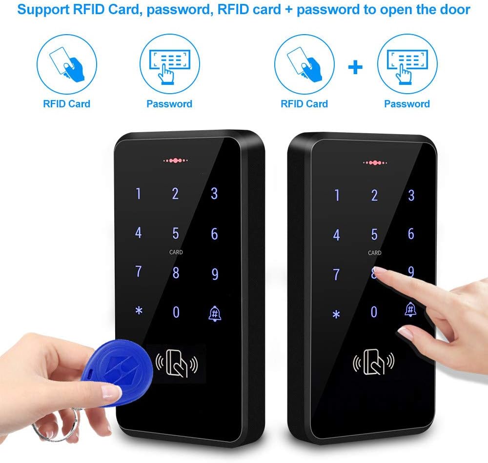
Image 8: The access control keypad displaying its blue backlight, which enhances visibility of the digits in dark conditions.
Maintenance
Regular maintenance ensures the longevity and reliable operation of your access control system.
- Cleaning: Wipe the keypad and exit button surfaces with a soft, damp cloth. Avoid abrasive cleaners or solvents that could damage the finish or electronics.
- Environmental Protection: While the keypad is IP68 waterproof, ensure the power supply unit is installed in a dry, protected area, as it is not waterproof.
- Cable Inspection: Periodically check all wiring for signs of wear, damage, or loose connections. Repair or replace damaged cables immediately.
- Keyfob Care: Keep RFID keyfobs away from strong magnetic fields and extreme temperatures to prevent damage.
Troubleshooting
This section addresses common issues you might encounter with your access control system.
1. System Not Powering On
- Check Power Source: Ensure the AC input to the power supply is active (100-260V).
- Verify Connections: Confirm all power cables from the power supply to the keypad are securely connected.
- Power Supply Indicator: Check if the "POWER" indicator light on the power supply unit is illuminated.
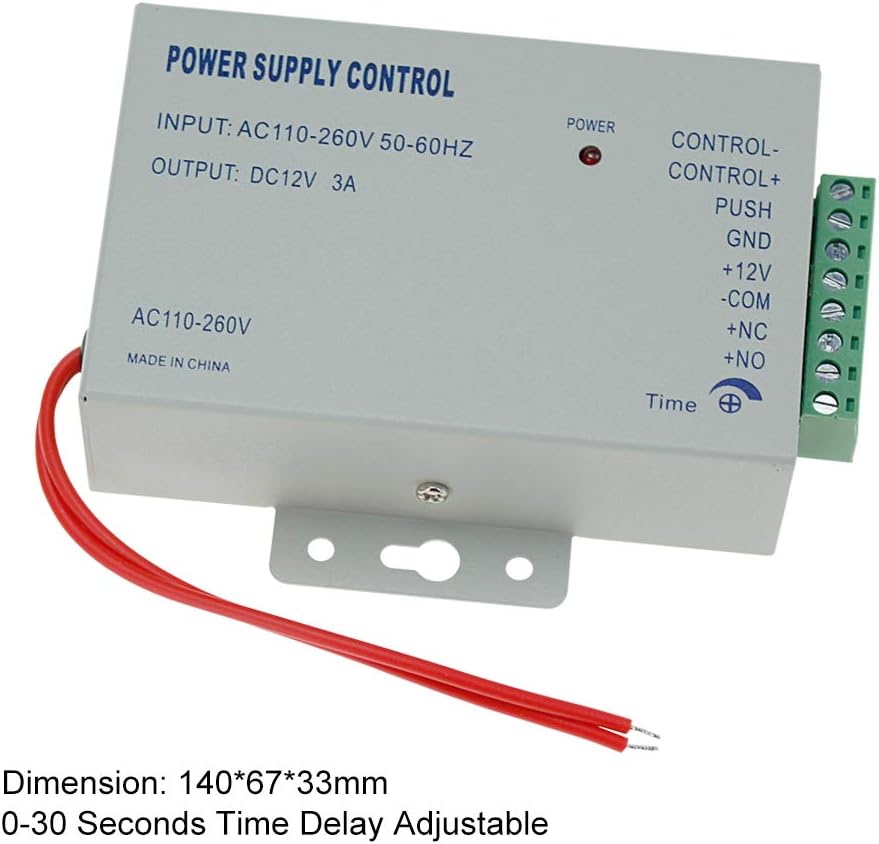
Image 9: The power supply control unit, showing input/output specifications and connection terminals.
2. Door Not Unlocking
- Wiring Check: Re-examine the wiring diagram (Image 5) carefully. Ensure the electric lock is correctly connected to the NC/NO terminals on the power supply.
- Jumper Position: Verify the jumper on the power supply is correctly set, especially if using a "PUSH" type lock. Incorrect jumper settings are a common cause of this issue.
- Lock Functionality: Test the electric lock independently to ensure it is functioning correctly.
- Access Credentials: Confirm the RFID card or password used is correctly programmed into the system.
- Door Opening Time: Check the door opening time setting (0-255 seconds) on the keypad. Ensure it's not set to 0 or an extremely short duration.
3. RFID Card Not Detected
- Card Programming: Ensure the RFID card has been successfully programmed into the keypad.
- Card Type: Verify that the card is an EM compatible 125KHz RFID card.
- Reading Distance: Hold the card within the 0-10cm reading range of the keypad.
4. Keypad Buttons Unresponsive
- Power Cycle: Disconnect and reconnect power to the system.
- Physical Damage: Inspect the keypad for any visible physical damage.
Warranty and Support
For warranty information, please refer to the terms and conditions provided at the time of purchase or contact your seller directly. If you encounter issues not covered in this troubleshooting guide, please reach out to the seller or manufacturer for technical assistance.


