Introduction
The Thsinde 19B Autoranging Digital Multimeter is a high-performance, high-precision, and highly reliable battery-driven automatic digital multimeter. Designed for professional electrical engineers, hobbyists, and home users, it offers a wide range of measurement capabilities including AC/DC voltage, AC/DC current, resistance, capacitance, frequency, temperature, diode, and continuity tests. Its robust design, large LCD display with backlight, and advanced features like True RMS measurement make it an ideal tool for laboratories, factories, and general electrical troubleshooting.
Safety Information
Please read and understand all safety information before operating this multimeter. Failure to follow these instructions may result in electric shock, fire, or damage to the meter.
- Always ensure the test leads are properly connected and the function switch is set to the correct range before making any measurements.
- Do not exceed the maximum input values for any range.
- Exercise extreme caution when working with voltages above 30V AC RMS, 42V peak, or 60V DC. These voltages pose a shock hazard.
- Before measuring current, ensure the circuit is de-energized and the meter is connected in series with the load.
- Always disconnect the test leads from the circuit before changing the function switch position.
- Do not use the meter if it appears damaged or if the test leads are damaged.
- Replace the battery when the low battery indicator appears to ensure accurate readings.
- The multimeter features a ceramic insurance tube for circuit protection. Do not attempt to bypass or modify this safety feature.
Package Contents
Verify that all items listed below are present in your package:
- Thsinde 19B Digital Multimeter
- Test Leads (Red and Black)
- 9V Battery (pre-installed or included)
- Temperature Probe (Thermocouple)
- Protective PVC Case / Carrying Pouch
- User Manual (this document)

Image: The Thsinde 19B Digital Multimeter shown with its included accessories, including the test leads, 9V battery, and a protective carrying case.
Product Overview
Familiarize yourself with the components of your Thsinde 19B Digital Multimeter.

Image: A detailed diagram labeling the various parts of the multimeter, including the Bright larger LCD, Range button, Hold/Light button, Select button, Function switch, 10A Jack, uA/mA Jack, COM Jack, Input Jack, Relative button, Hz/Duty button, Max/Min button, and Rubble sleeve.
- LCD Display: Large, clear, and backlit display for easy reading of measurements.
- Function Switch: Rotary dial to select the desired measurement function (e.g., Voltage, Current, Resistance, Temperature).
- Input Jacks:
- COM (Common) Jack: For the black test lead.
- VΩHz Jack: For the red test lead when measuring voltage, resistance, frequency, capacitance, diode, and continuity.
- mAµA Jack: For the red test lead when measuring small currents (milliamperes, microamperes).
- 10A Jack: For the red test lead when measuring large currents (up to 10 Amperes).
- Buttons:
- HOLD/Light: Freezes the current display reading; long press activates/deactivates backlight.
- RANGE: Manually selects the measurement range (overrides autoranging).
- RELΔ (Relative): Measures the difference between a stored value and the current reading.
- Hz/%: Toggles between frequency and duty cycle measurement.
- MAX/MIN: Records maximum and minimum readings.
- SELECT: Toggles between different measurement types within a single function switch position (e.g., AC/DC voltage, diode/continuity).
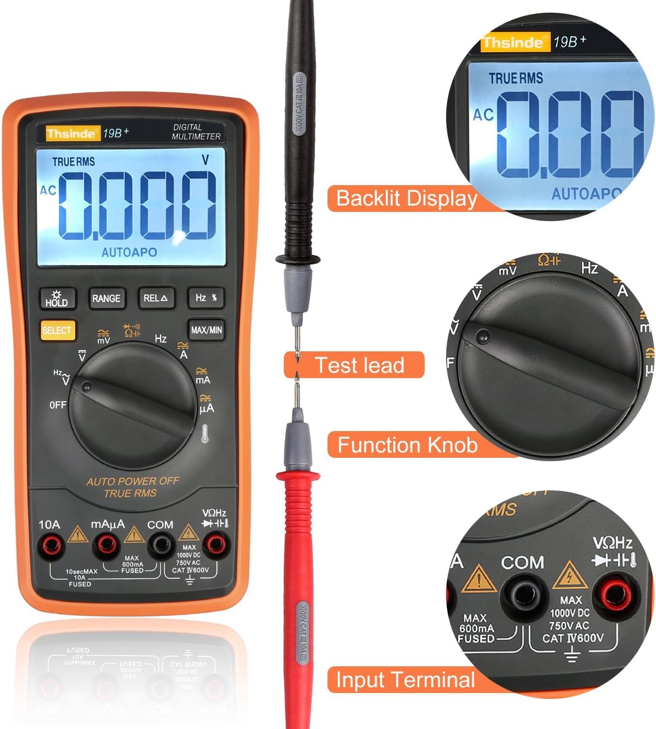
Image: This image highlights the backlit display, the connection of a test lead, the function knob, and the input terminals of the multimeter.

Image: An internal view of the multimeter, revealing its double-sided gold plated PCB board, intelligence IC chips, electrolytic capacitors, high-precision manganese copper resistance, double explosion-proof ceramic tube, protection resistors, cell contact point, temperature sensing, and solid tester lead input receptacles.
Setup
1. Battery Installation
The Thsinde 19B Multimeter typically comes with a 9V battery pre-installed or included. If not installed, follow these steps:
- Ensure the multimeter is turned OFF.
- Locate the battery compartment cover on the back of the meter.
- Use a screwdriver to remove the screw securing the cover.
- Carefully remove the cover.
- Connect the 9V battery to the battery clip, observing correct polarity (+ to + and - to -).
- Place the battery into the compartment.
- Replace the battery compartment cover and secure it with the screw.
2. Connecting Test Leads
Always connect the black test lead to the COM (common) input jack. Connect the red test lead to the appropriate input jack based on the measurement you intend to make:
- For Voltage, Resistance, Capacitance, Frequency, Diode, and Continuity measurements: Connect the red lead to the VΩHz jack.
- For Current measurements (mA/µA): Connect the red lead to the mAµA jack.
- For High Current measurements (10A): Connect the red lead to the 10A jack.
Operating Instructions
This section provides detailed instructions for performing various measurements with your Thsinde 19B Digital Multimeter.
1. Measuring AC/DC Voltage (V)
- Connect the black test lead to the COM jack and the red test lead to the VΩHz jack.
- Turn the function switch to the V~ (AC Voltage) or V- (DC Voltage) position. If the symbol is combined, press the SELECT button to toggle between AC and DC.
- Connect the test probes in parallel across the component or circuit you wish to measure.
- Read the voltage value on the LCD display.
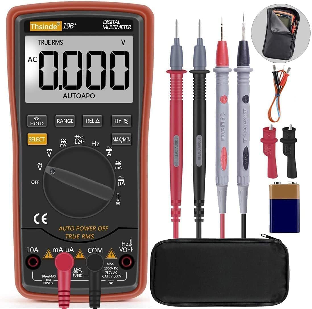
Image: The Thsinde 19B Multimeter displaying an AC voltage reading, demonstrating its capability to measure alternating current voltage.
2. Measuring AC/DC Current (A)
- Important: De-energize the circuit before connecting the meter.
- Connect the black test lead to the COM jack.
- For currents up to 600mA, connect the red test lead to the mAµA jack. For currents up to 10A, connect the red test lead to the 10A jack.
- Turn the function switch to the appropriate A~ (AC Current) or A- (DC Current) position. Use the SELECT button if needed.
- Break the circuit and connect the test probes in series with the load.
- Re-energize the circuit and read the current value on the LCD display.
3. Measuring Resistance (Ω)
- Connect the black test lead to the COM jack and the red test lead to the VΩHz jack.
- Turn the function switch to the Ω (Resistance) position.
- Ensure the component is de-energized before measuring. Connect the test probes across the component.
- Read the resistance value on the LCD display.
4. Continuity Test
- Connect the black test lead to the COM jack and the red test lead to the VΩHz jack.
- Turn the function switch to the Ω (Resistance) position and press SELECT until the continuity symbol (speaker icon) appears.
- Connect the test probes across the circuit or component. A continuous beep indicates a good connection (low resistance).
5. Measuring Capacitance (F)
- Connect the black test lead to the COM jack and the red test lead to the VΩHz jack.
- Turn the function switch to the Capacitance position (often shared with diode/continuity, use SELECT to cycle).
- Ensure the capacitor is fully discharged before testing. Connect the test probes across the capacitor terminals.
- Read the capacitance value on the LCD display.
6. Measuring Frequency (Hz)
- Connect the black test lead to the COM jack and the red test lead to the VΩHz jack.
- Turn the function switch to the Hz position (often shared with voltage or current, use Hz/% button to activate).
- Connect the test probes in parallel with the circuit where you want to measure frequency.
- Read the frequency value on the LCD display.
7. Diode Test
- Connect the black test lead to the COM jack and the red test lead to the VΩHz jack.
- Turn the function switch to the Diode position (often shared with continuity, use SELECT to cycle).
- Connect the red probe to the anode and the black probe to the cathode of the diode. A forward voltage drop will be displayed. Reverse the probes; an open circuit (OL) indicates a good diode.
8. Measuring Temperature
- Connect the temperature probe (thermocouple) to the VΩHz and COM jacks, observing polarity if indicated.
- Turn the function switch to the Temperature position (indicated by a thermometer symbol).
- The display will show the ambient temperature. Place the tip of the temperature probe on the object or in the environment you wish to measure.
- The multimeter can switch between Fahrenheit and Celsius.
- Read the temperature value on the LCD display.

Image: The Thsinde 19B Multimeter actively measuring temperature, displaying "0022" degrees Celsius, with a range of -20°C to 1000°C (0°F to 1832°F) indicated.
Maintenance
Cleaning
Wipe the meter casing with a damp cloth and mild detergent. Do not use abrasives or solvents. Keep the input jacks free of dust and debris.
Battery Replacement
When the low battery indicator appears on the display, replace the 9V battery as described in the "Battery Installation" section under Setup. Always use a fresh 9V battery.
Storage
If the meter is not to be used for an extended period, remove the battery to prevent leakage and damage. Store the meter in its protective case in a cool, dry place, away from direct sunlight and extreme temperatures.
Troubleshooting
| Problem | Possible Cause | Solution |
|---|---|---|
| Meter does not turn on. | Dead or improperly installed battery. | Check battery installation; replace battery. |
| "OL" (Overload) displayed. | Measurement exceeds selected range or meter's maximum capacity. | Switch to a higher range or ensure measurement is within meter's limits. |
| Inaccurate readings. | Low battery; incorrect function/range selected; poor test lead connection. | Replace battery; verify function/range; ensure secure connections. |
| No continuity beep. | Open circuit; meter not in continuity mode. | Check circuit; press SELECT to activate continuity mode. |
Specifications

Image: The Thsinde 19B Multimeter with overlaid dimensions, showing its height of 18.5cm (7.28 inches) and LCD screen dimensions of 6.5cm (2.56 inches) by 4cm (1.57 inches).
| Feature | Detail |
|---|---|
| Brand | Thsinde |
| Model | 19B (TH053) |
| Measurement Type | Multimeter (Autoranging) |
| Power Source | 9V Battery (included) |
| Display | Large LCD with Backlight |
| Sampling Speed | 3 times per second |
| True RMS | Yes |
| Overload Protection | Ceramics Protection Circuit |
| AC Voltage Range | Up to 750V AC |
| DC Voltage Range | Up to 1000V DC |
| Temperature Range | -20°C to 1000°C (0°F to 1832°F) |
| Item Weight | 320 Grams (approx. 11.3 ounces) |
| Dimensions | 8.78 x 6.38 x 2.44 inches (Package) |
| Material | ABS with PVC protective case |
Warranty and Support
Thsinde products are designed for reliability and performance. For any technical support or warranty inquiries, please contact Thsinde customer service through the retailer where the product was purchased or refer to the contact information provided on the product packaging or official Thsinde website.
Please retain your proof of purchase for warranty claims.